Analysis and design of masonry constructions
SCADA Pro Masonry +
Unified application of static and dynamic analysis, design and evaluation of load-bearing masonry structures
Detailed Description
SCADA Pro Masonry is a complete and comprehensive application for static and dynamic analysis and design of masonry structures according to Eurocode 6 and most European National Annexes.
It consists of the basic suite (SCADA Pro Analysis) and the additional tool for the design of masonry structures according to EC6.
It also includes the production of the full repost of the project.
Interface
New interface for even more flexibility and productivity
Invest and learn a single application that will meet all your needs for the analysis and design of any structural project with different materials.
SCADA Pro, based on Microsoft Ribbon technology, offers a unified, innovative and beautiful user interface, where it is easier to use more commands in a fully customizable environment.
Ribbons allow for visual layout and grouping of the commands in order to enable the user to discover and use the application’s tools easier, faster, and more efficiently.
On the left side of the interface, all the structure entities are shown in a tree form, categorized either per storey (level) or for the entire structure. This categorization helps in tracking any member of the structure by just selecting it on the tree which displays it in different color on the structural model.
The member’s storey is, then, isolated, and on the right side of the interface its properties are shown, with live editing capability. This process can be applied interactively, that is the member can be selected graphically on the structural model and this member’s properties will appear on the right side of the interface.
Additionally, a list of optional commands can be applied on each tree member selected. The optional context sensitive menu appears when right clicking, to help the user find features fast.
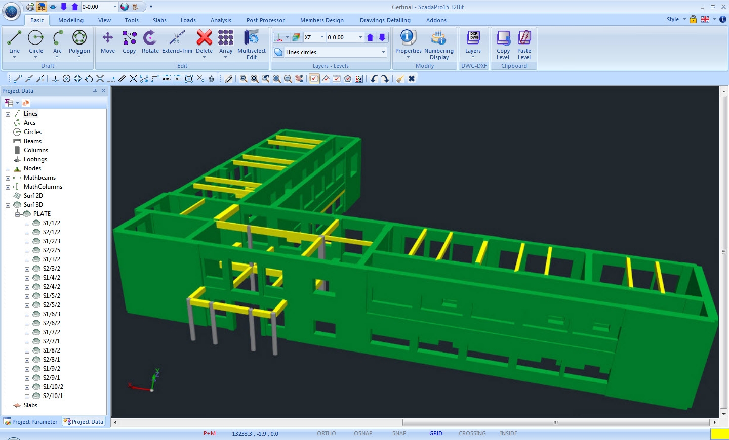
Modelling
Automatic recognition of structural elements and creation of the structure from DXF, DWG file.
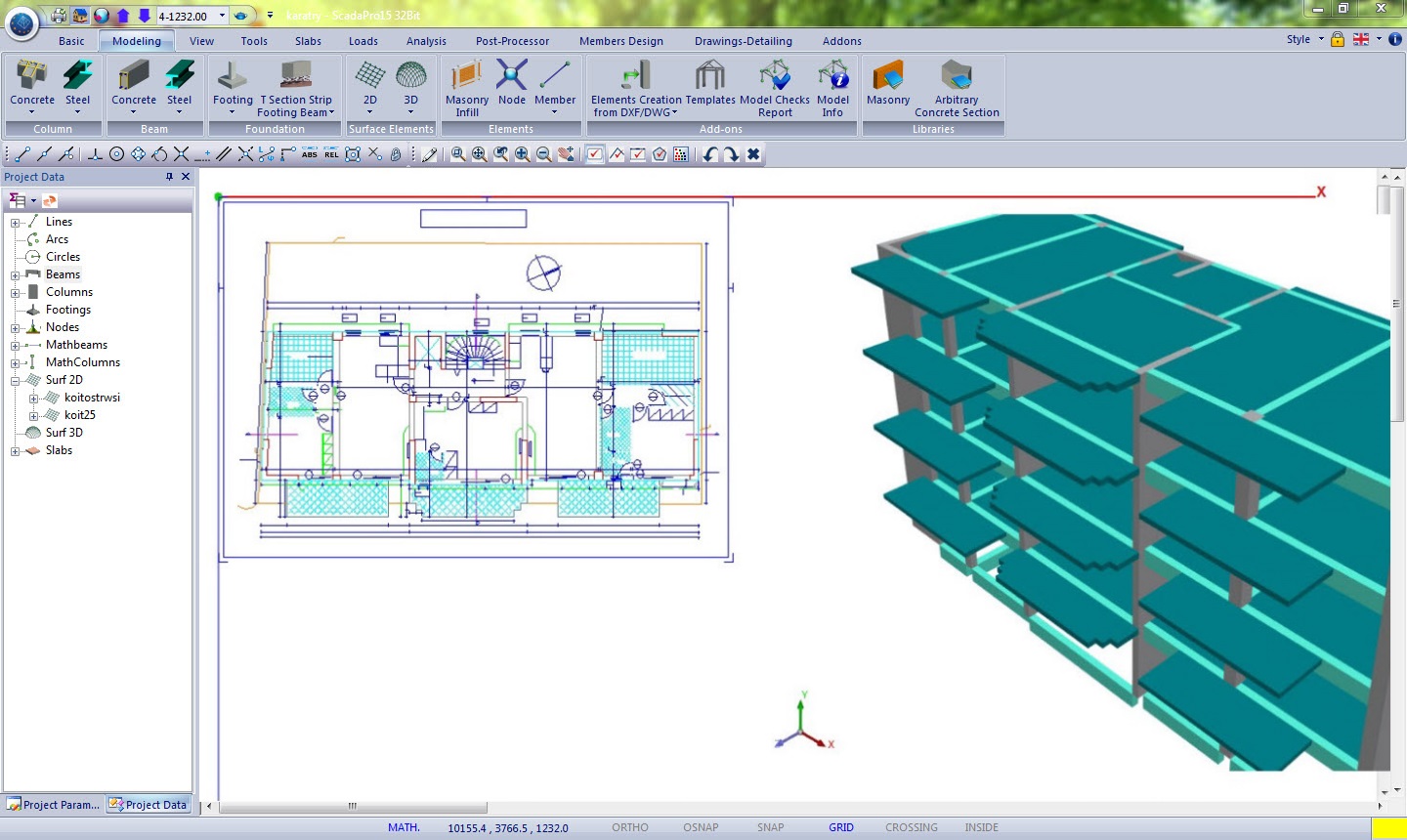
Minimizing time for data input
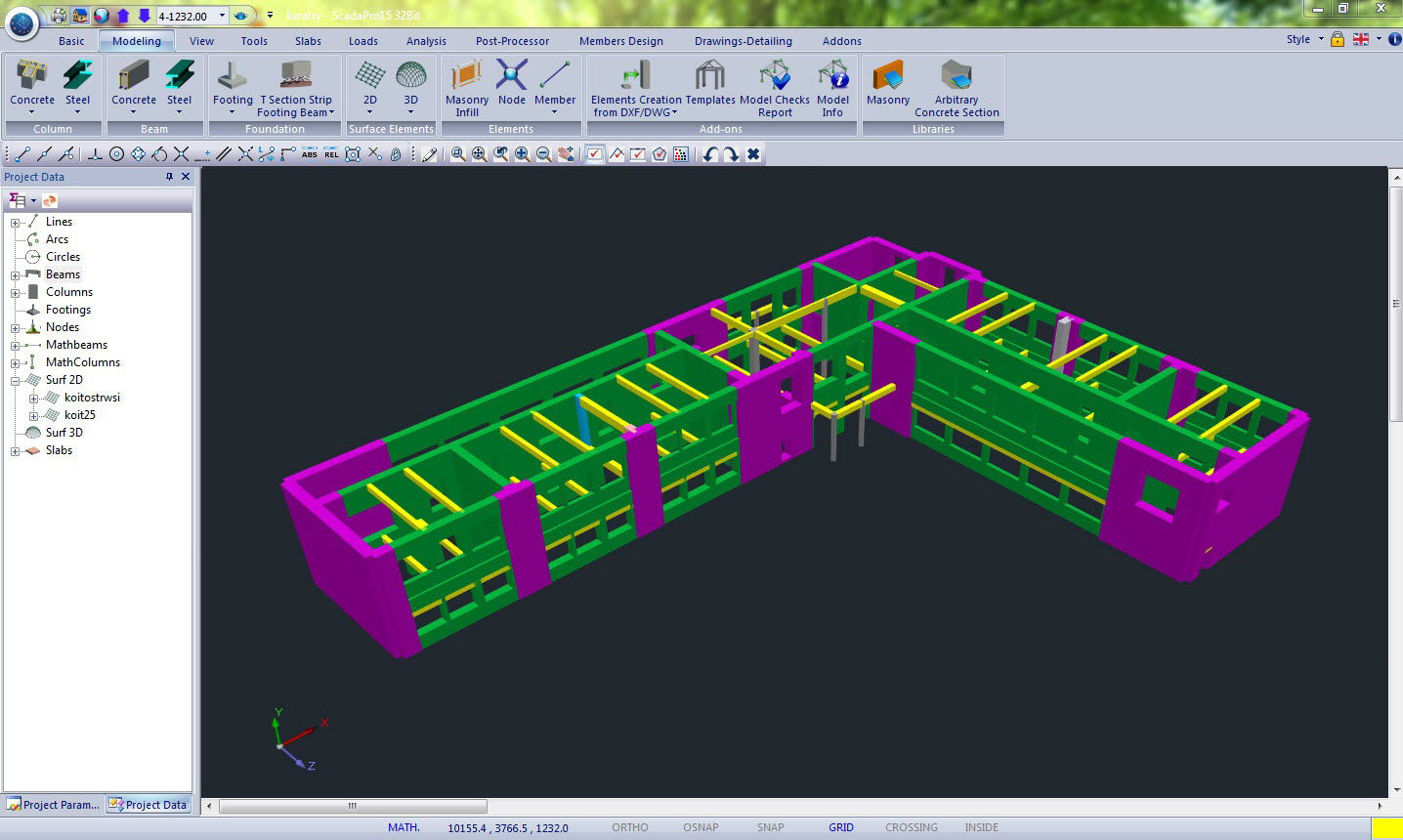
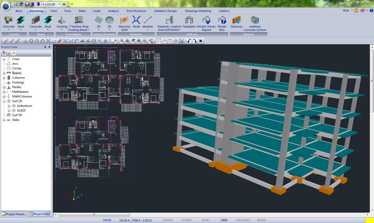
SCADA Pro, beautiful and productive interface offers automatic recognition of physical cross-sections from any architectural drawing in DXF or DWG form.
Recognition and modelling using the cross-sections of the SCADA Pro library can be applied selectively or automatically per storey, per structural member (Columns, Beams, Strip Foundations, Footings) or for the entire structure.
Furthermore, the structure’s slabs are identified automatically, as well as all cantilevers drawn in simple lines.
Full compatibility between AutoCAD Revit Structure Suite and SCADA Pro,
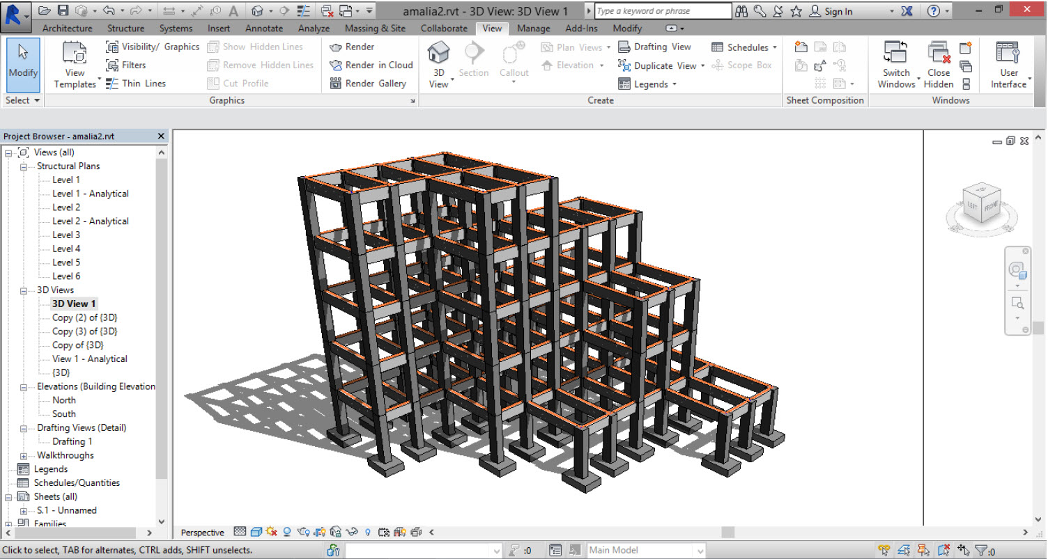
AutoCAD Revit Structure Suite includes a complete set of applications for the structural model generation.
Bidirectional communication with SCADA Pro offers an easy way to import, through ifc files, 3D architectural models ready for analysis.
All structural members, columns, beams etc. as well as the loads and steel connections, automatically and accurately are converted to their respective structural elements of SCADA Pro.
Bidirectional communication between architectural and structural models ensures time savings and cost reduction.
SCADA Pro has been certified by Autodesk for the automatic, bidirectional communication interface with Revit Structure.
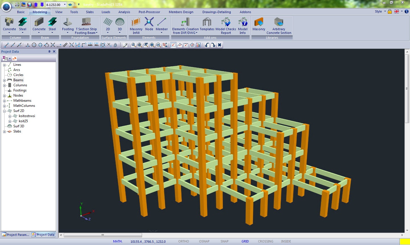
3D FEM
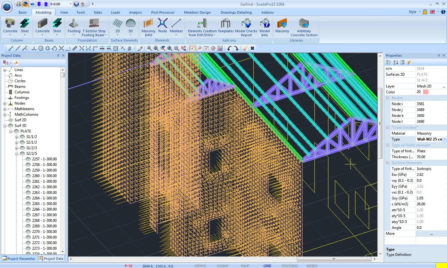
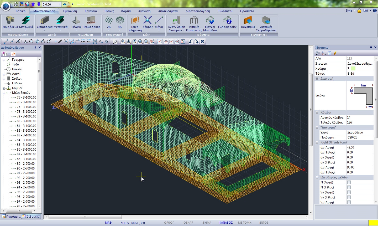
New powerful mesh generator of 3D surface finite elements
A new mesh generator of 3D surface finite elements is included in SCADA Pro.
Surfaces of any shape may be modelled and the meshing is completed regardless the pattern of holes or concentration points on a surface.
The mesh generation is automatic even when both surface and linear elements are present (nodes of neighboring linear and surface elements are automatically merged together).
The ability of inserting a point for adaptation of the mesh around it is also available.
The program also allows the insertion of a hole in an already meshed surface.
Any type of material may be attributed to a mesh with no problem.
Contours concerning the stress resultants, the strains or the computed reinforcement percentage “As” may be drawn on the produced mesh.
Loads
Input loads for the structure: Direct load definition on members using any load type desired.
SCADA Pro gives the user the option to input graphically, on members, the loads desired.
All load types are supported, e.g. uniformly distributed forces, concentrated forces, nodal forces, torsional moments, settlement, thermal actions etc.
Loading and combinations required by EC 0 are automatically calculated, with full editing options for the user.
Automatic generation of wind and snow loads according to EC1, as well as automatic attribution to the members with respective generation of load cases, ready for analysis.
Input of slabs and slab loads
The identifications of the slabs in SCADA Pro is accomplished automatically by the automatic assignment of the support conditions.
Slabs of any shape and any type are considered (Conventional, Zoellner, Sandwich).
There is also available the feature of converting a conventional slab to a slab simulated with finite surface elements.
The minimum thickness of the slab is calculated automatically applying the slenderness control.
The loads on the slabs can be imported in total for all slabs or selectively with instant processing and modification.
The loads can be imported as linear or in segments.
The assignment of loads is done with a single click on the columns and the footing beams with corresponding appearance of leakage lines and influence surfaces per structural member.
The loads on members are calculated through Marcus coefficient method according to the slab’s support conditions.
Analysis Types
Fast and reliable solvers so that the user can rely on
SCADA Pro incorporates more than 30 years of know-how from ACE-Hellas advanced research and development team. It utilizes the most powerful solvers for all analysis methods and is using advanced parallel processing components to minimize execution time.
The following analysis methods are included:
Linear Simplified Spectral Method (Equivalent Spectral Method)
The linear simplified spectral method refers to the calculation of the displacements, deformations and the internal forces of the structure under static loads.
The calculation of the response is carried out by solving the linear system of equations which describes the model of the structure.
The externally imposed loads can be point on the nodes or distributed along the members, while the self-weight of the structure is taken into account.
The results of the linear static method can be used for the design of the structure, using the parameters provided by each regulation.
Linear Dynamic Spectral Method
The linear dynamic spectral method is a simplified approximate analysis method, which uses superposition of the eigenmodes for the estimation of the maximum response of the structure, under earthquake excitation.
Using this methodology the complete calculation of the response time histories, required in dynamic analyses, is avoided.
Instead, the spectral values of the response which correspond to each eigenmode are calculated.
The value of the maximum response is next estimated using statistical analysis, since the maximum response of each eigenmode does not occur on the same time, but also the exact time is not known.
The great advantage of the spectral dynamic method is the fact that it requires a reduced amount of eigenmodes for the estimation of the structure’s response and therefore reduced computational cost.
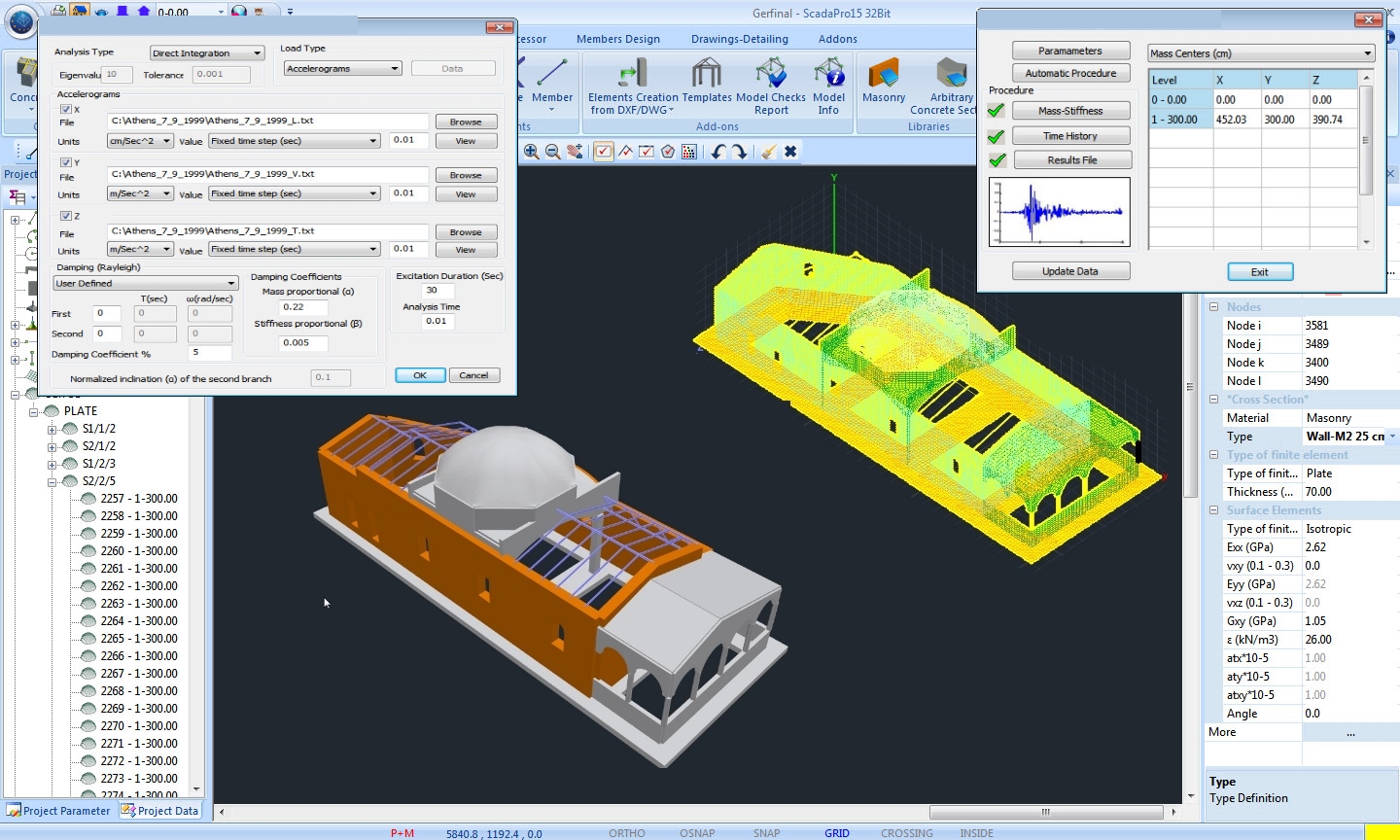
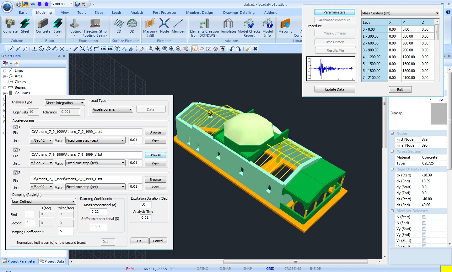
Linear Dynamic Time History Analysis
Time history dynamic analysis refers to the calculation of the structure’s response under a predefined external load which varies in time (earthquake excitation).
Time history dynamic analysis is divided into linear and nonlinear.
It is considered as linear when all the structural members behave elastically and therefore the structure responds linearly to the imposed loads.
For the calculation of the response, the structural equations of motion have to be solved.
This can be done in two ways: modal analysis or direct integration of the equations of motion.
As far as the modal analysis is concerned, a reduced amount of eigenmodes that contribute to the response are chosen.
Normally, a quite small amount of eigenmodes with respect to the total degrees of freedom of the model, can lead to a satisfactory estimation of the time history response.
This leads to an important decrease of the computational cost.
As far as the direct integration method is concerned, the full mass, damping and stiffness matrices are used at the equations of motion, which are numerically integrated with respect to time.
The computational cost increases, but the solution obtained is exact and not approximate.
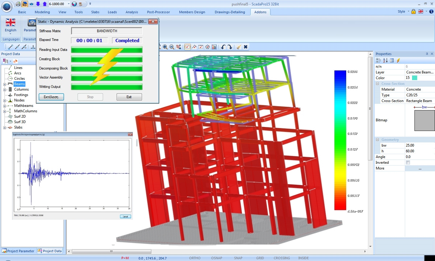
Non-Linear Dynamic Time History Analysis
Non-linear dynamic time history analysis is the most reliable methodology of the seismic behavior of structures.
For this analysis, models of the non-linear behavior of the structure’s materials are used, in order to properly simulate their fully inelastic and hysteretic behavior.
In order to estimate the structure’s response under seismic excitation, numerical integration of the equations of motion is required in time domain.
This type of analysis has high computational cost, but it is the only one that has the ability of estimating the inelastic deformations and internal forces under predefined earthquake loadings.
Due to its high accuracy, non-linear dynamic analysis can be used at every structure without limitations. But the response of the structure can present high sensitivity at the characteristics of each Imposed earthquake excitation.
For this reason it is recommended to repeat the analysis using more than one seismic events.
EC8 recommends that if less than seven seismic events have been analyzed, the user has to use the unfavorable scenario for the design of the structure, while in different cases the mean values of the response can be taken into account.
Multithreading CPU – GPU accelerated analysis
Analysis time of large models can take up to many hours or even days using traditional finite element and linear system technics. High Performance Computing (HPC) features can be used in order to reduce run times and efficiently solve large problems fast.
Analysis on multicore CPU or GPU
Run time can be reduced significantly by taking advantage of parallel solvers which run on multicore CPUs (Shared Memory Parallelism).
The solver divides the work into parts and each core (thread) takes over only one part, therefore solving the problem in parallel significantly faster.
For even better results, the graphics processor of a system can be used (such as an NVidia or AMD graphics card).
The main difference is that in multicore CPUs there are typically 2-8 threads, whereas in GPUs there are a few hundreds or even thousands of parallel threads.
This vast parallelism (fine-grained) leads to even lower analysis times for very large models.
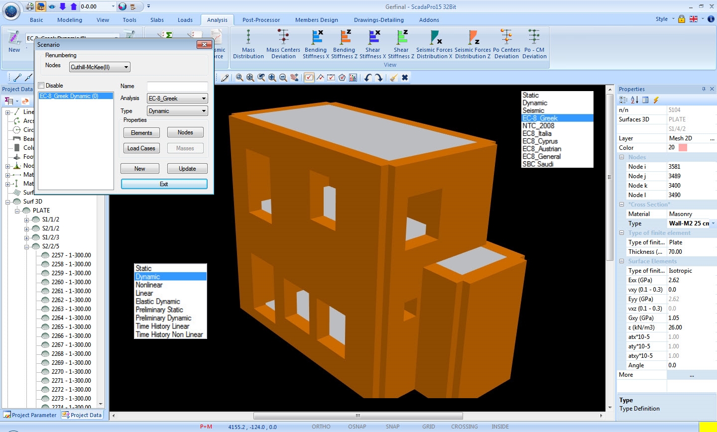
Analysis – Seismic design – Checks (EC8)
Full customization for repetitive analyses and result optimization. Try safely!
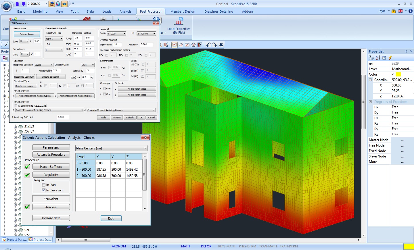
All the required by EC8 checks and the corresponding local regulations are presented in a way that is simple with complete oversight so that the user has a full overview of the entire structure.
In SCADA Pro the user can choose the desired analysis method and regulations, and the program applies automatically the predefined parameters required by the regulations.
Furthermore, the ability to fully customize the environment, allows the user to try out solutions and validate the effects of each parameter based on the final results.
Of course, all the solutions produced, through the different scenarios provided by the software, are saved and are available at any time, for direct comparison.
Execution of multiple analyses with a single click. Versatility and infinite options for the user.
SCADA Pro provides the user with the option to choose the desired analysis method in order to obtain the results fast and easy. It also provides the option to combine internal force values from different analysis methods!
Of course, all the load combinations are produced automatically, while allowing for editing whenever and however the user desires!
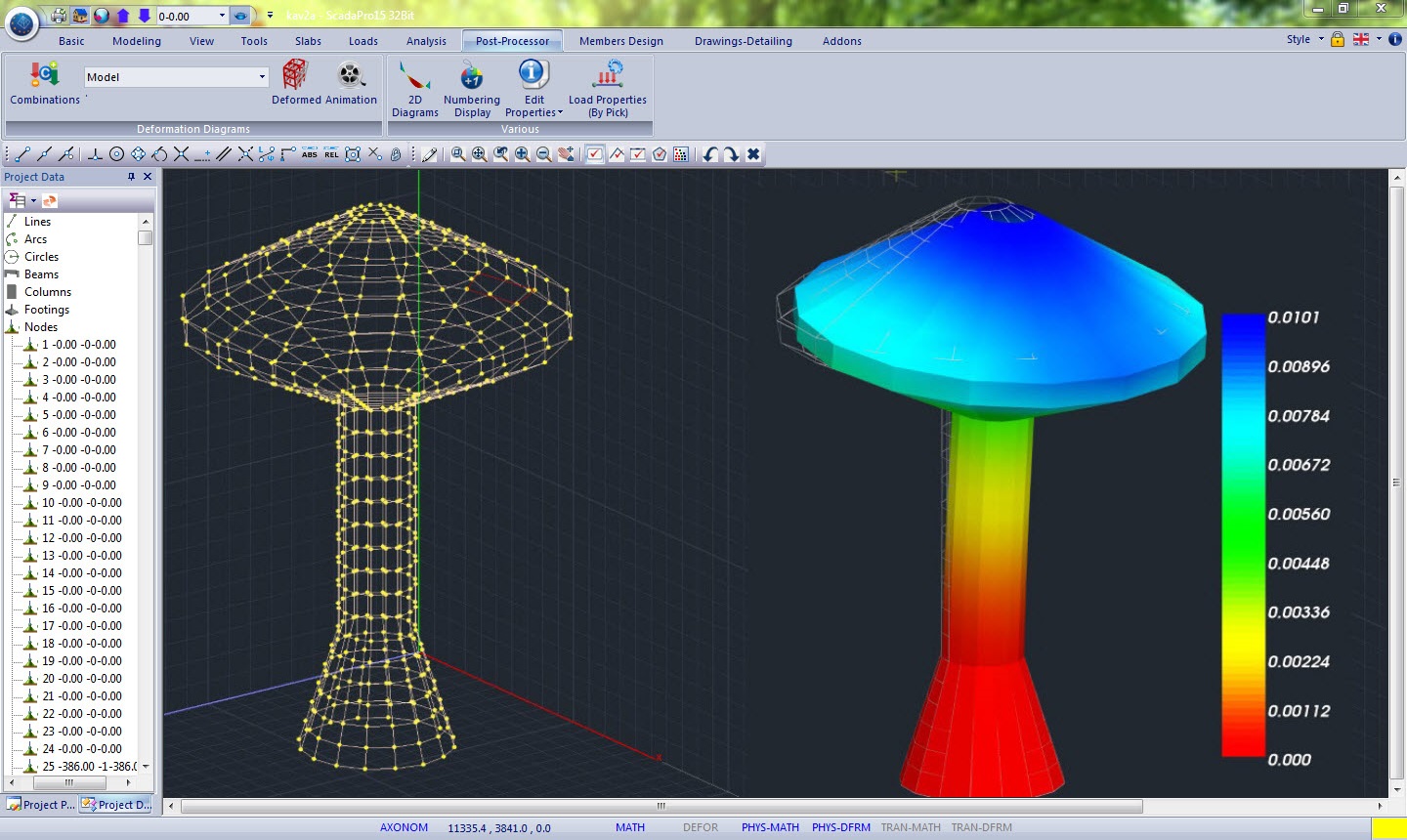
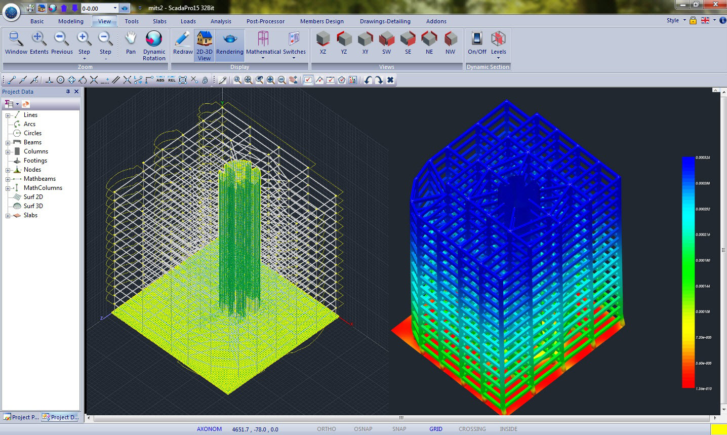
Results – Post Processing
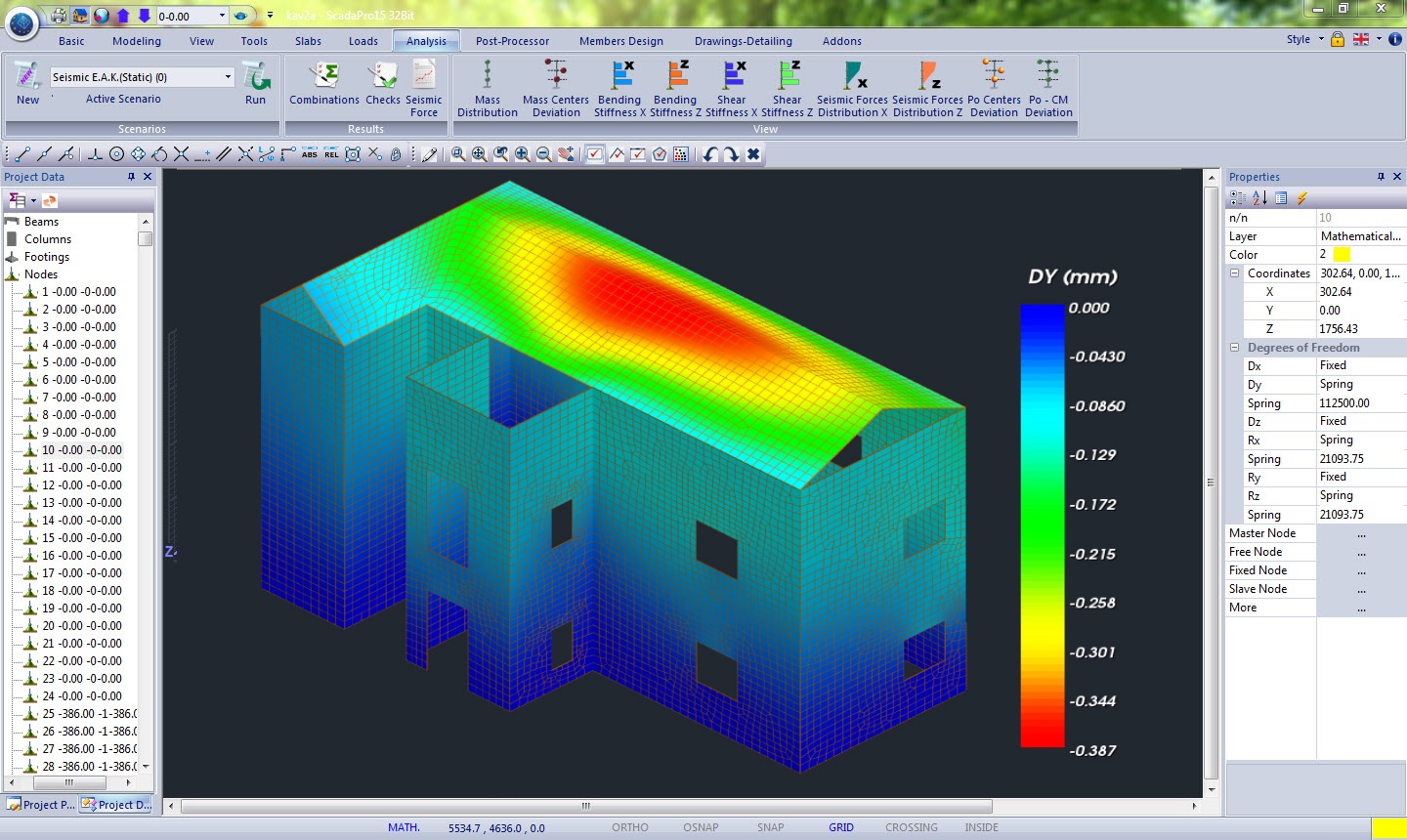
Three – dimensional visualization of the internal forces and deformed shape of the structure so that the user can have full oversight anytime
The results section, through a rich and fluent graphical interface, provides the user all the tools to view the structure, colored diagrams from any internal force and loading, load combination or envelope.
All the user have to do is to choose the view scale and locate fast and easily the members developing the maximum forces or deformations.
The user can also view the deformed structure with motion in space for any static or dynamic loading and eigenmode.
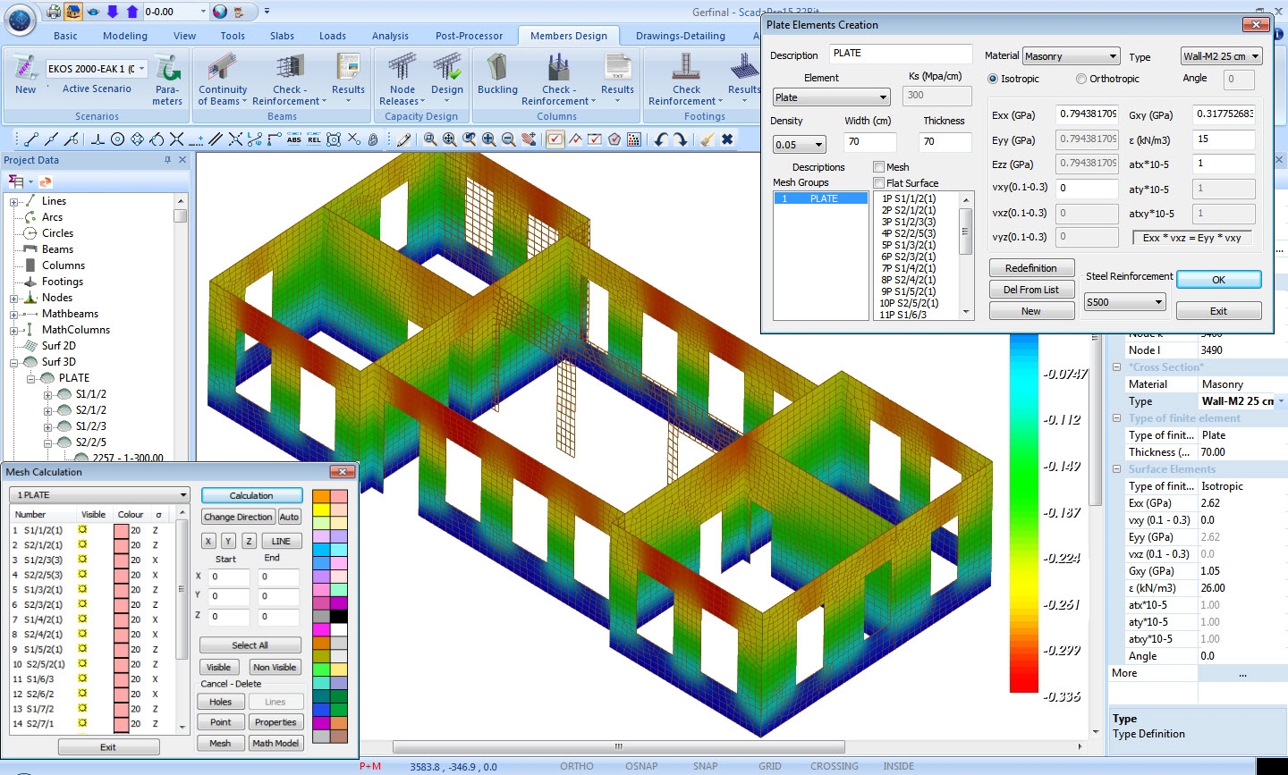
Furthermore, contour plots of the internal forces, deformations and steel reinforcement of surface finite elements are presented.
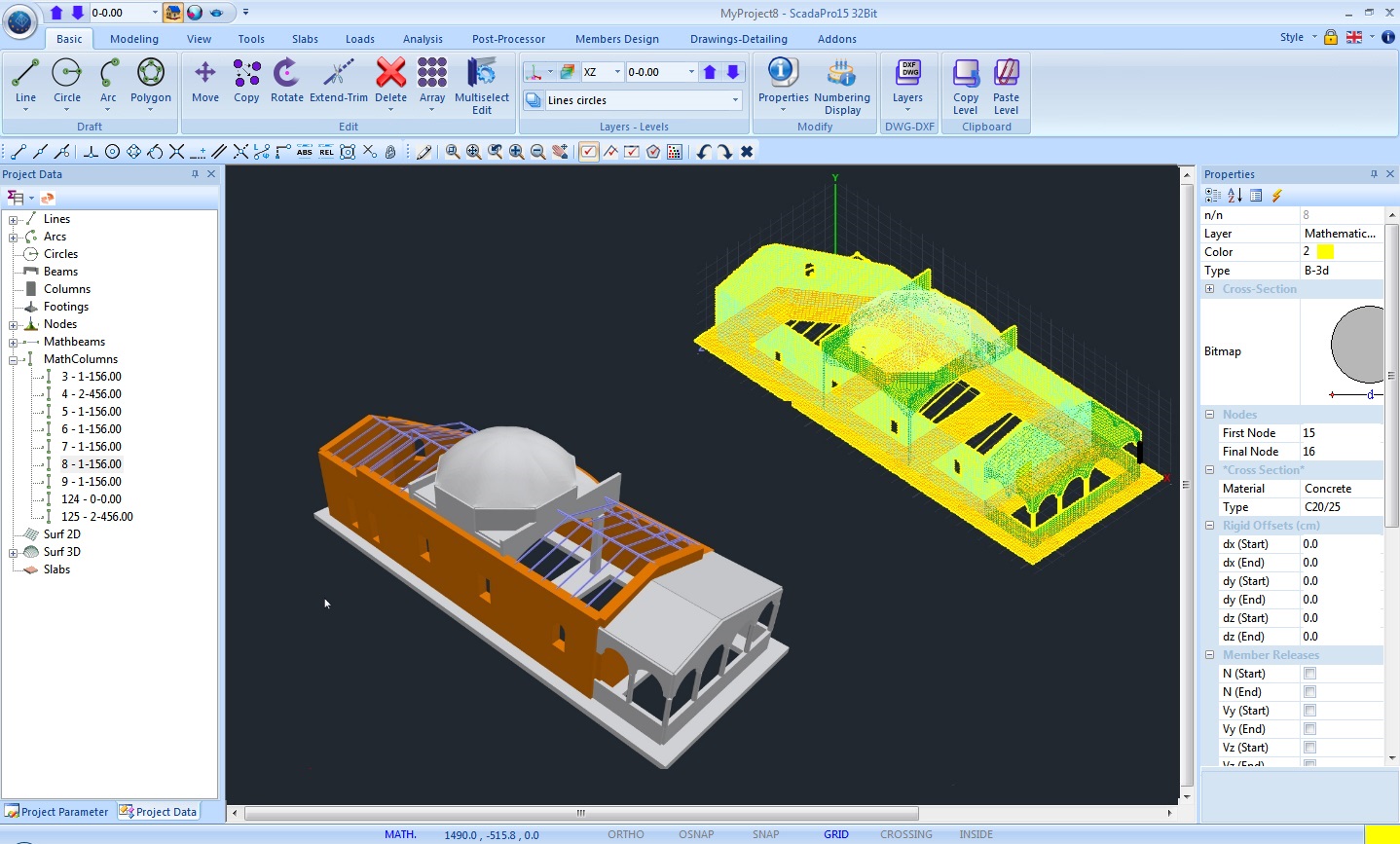
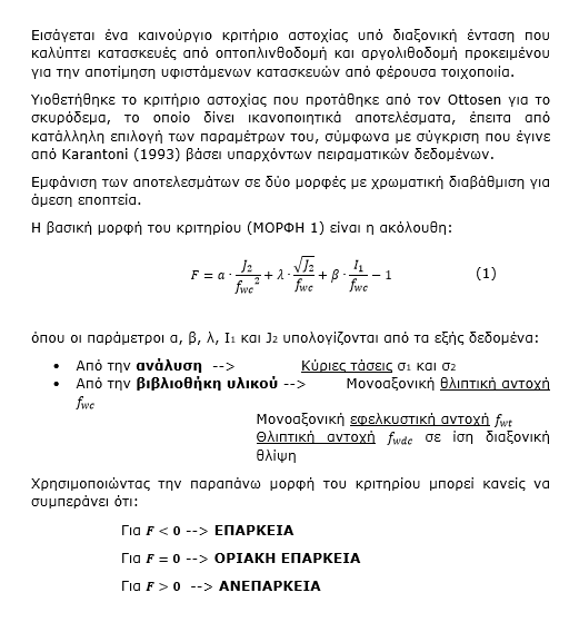
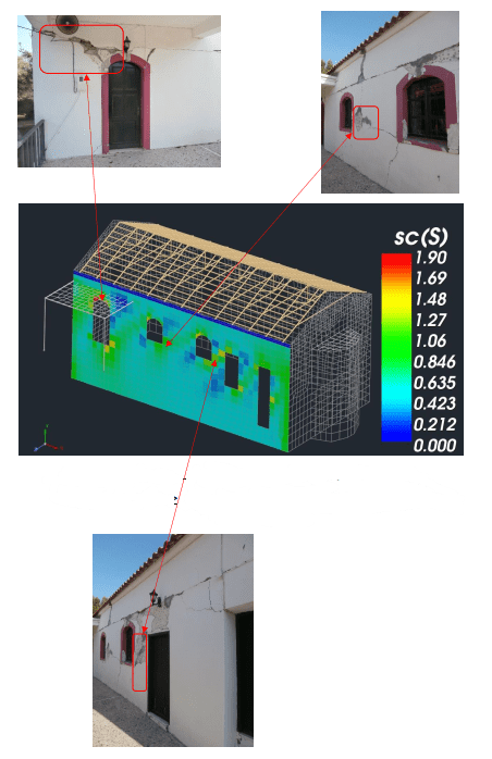
Αποτίμηση τοιχοποιίας με κριτήριο αστοχίας τάσεων
Design(EC6)
Analysis and design of loadbearing masonry structures according to EC6
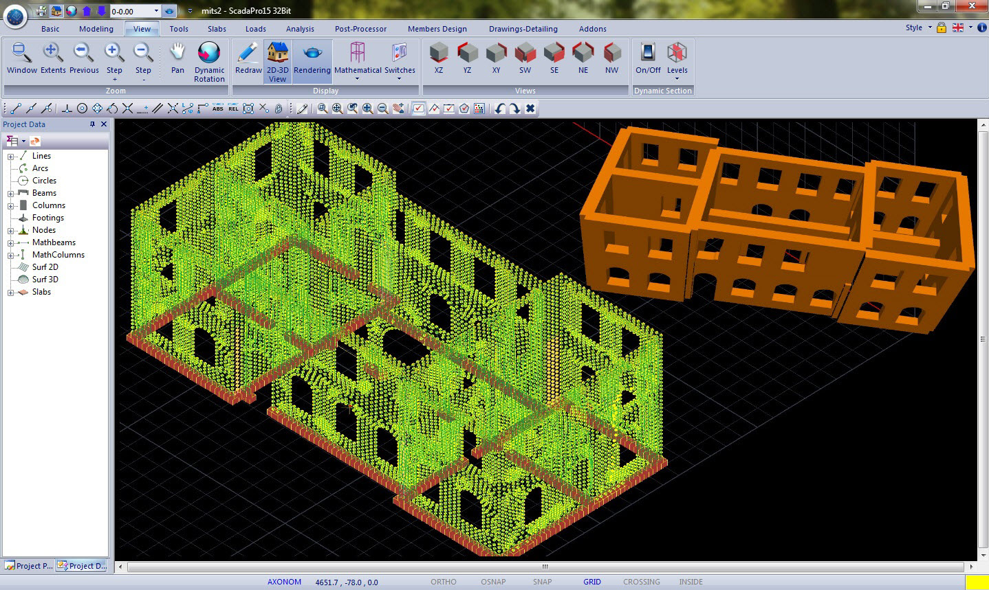
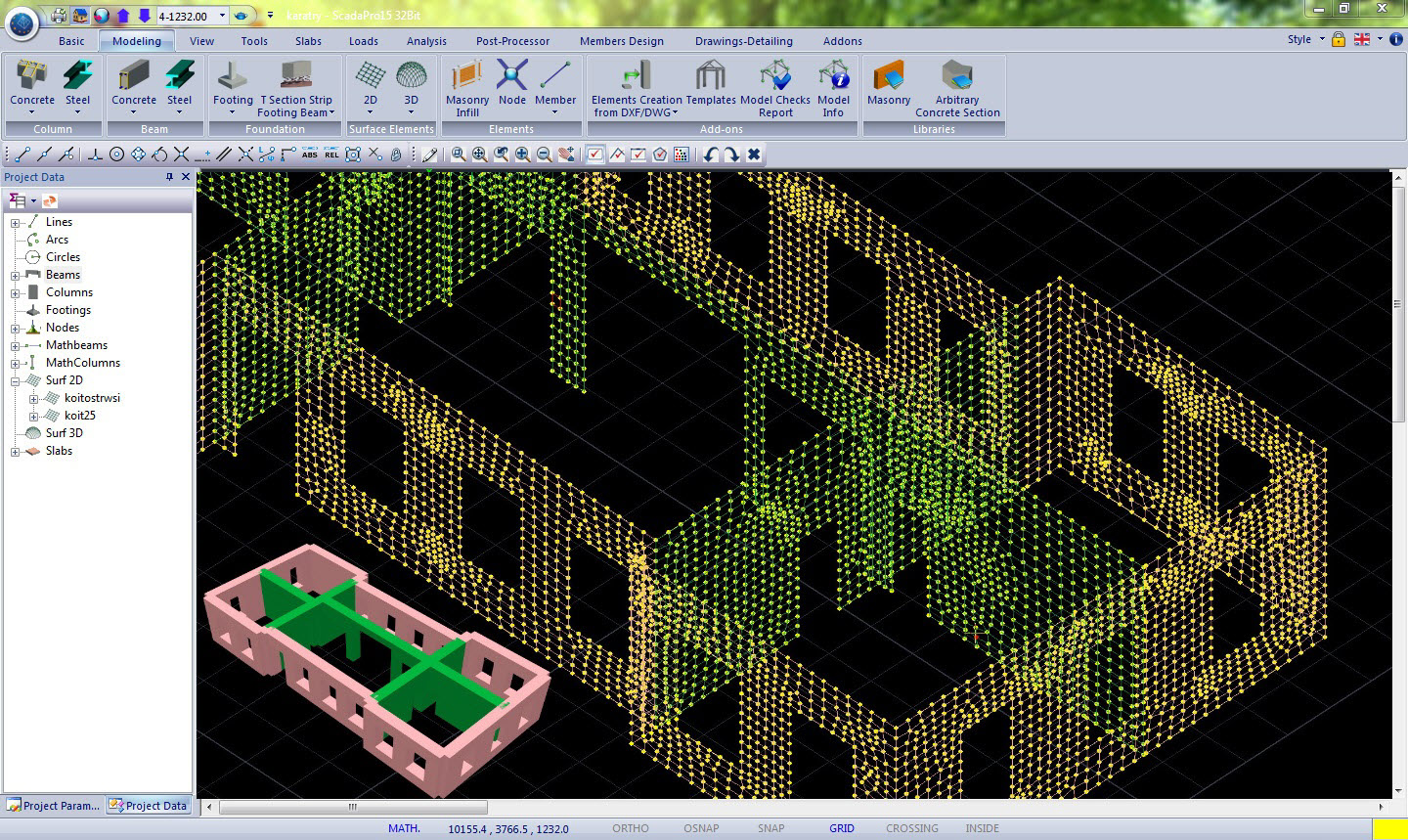
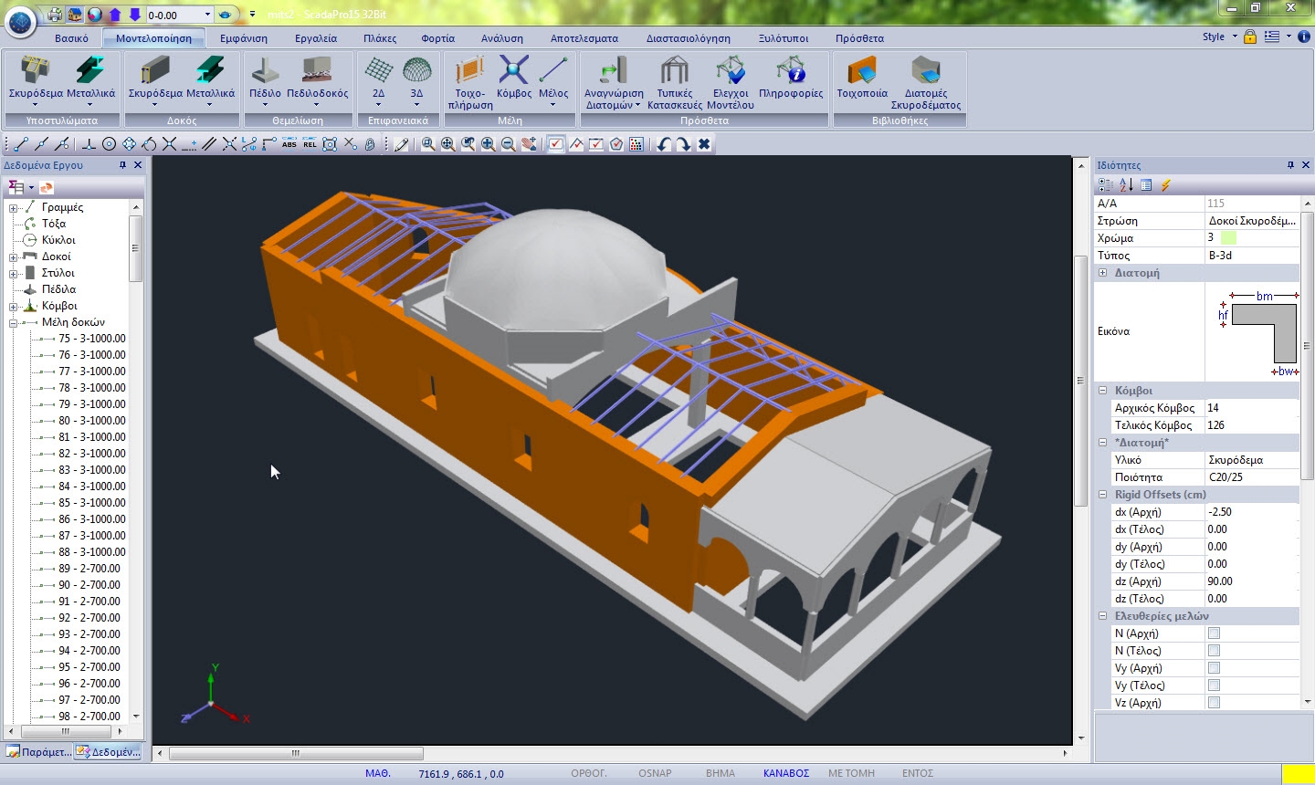
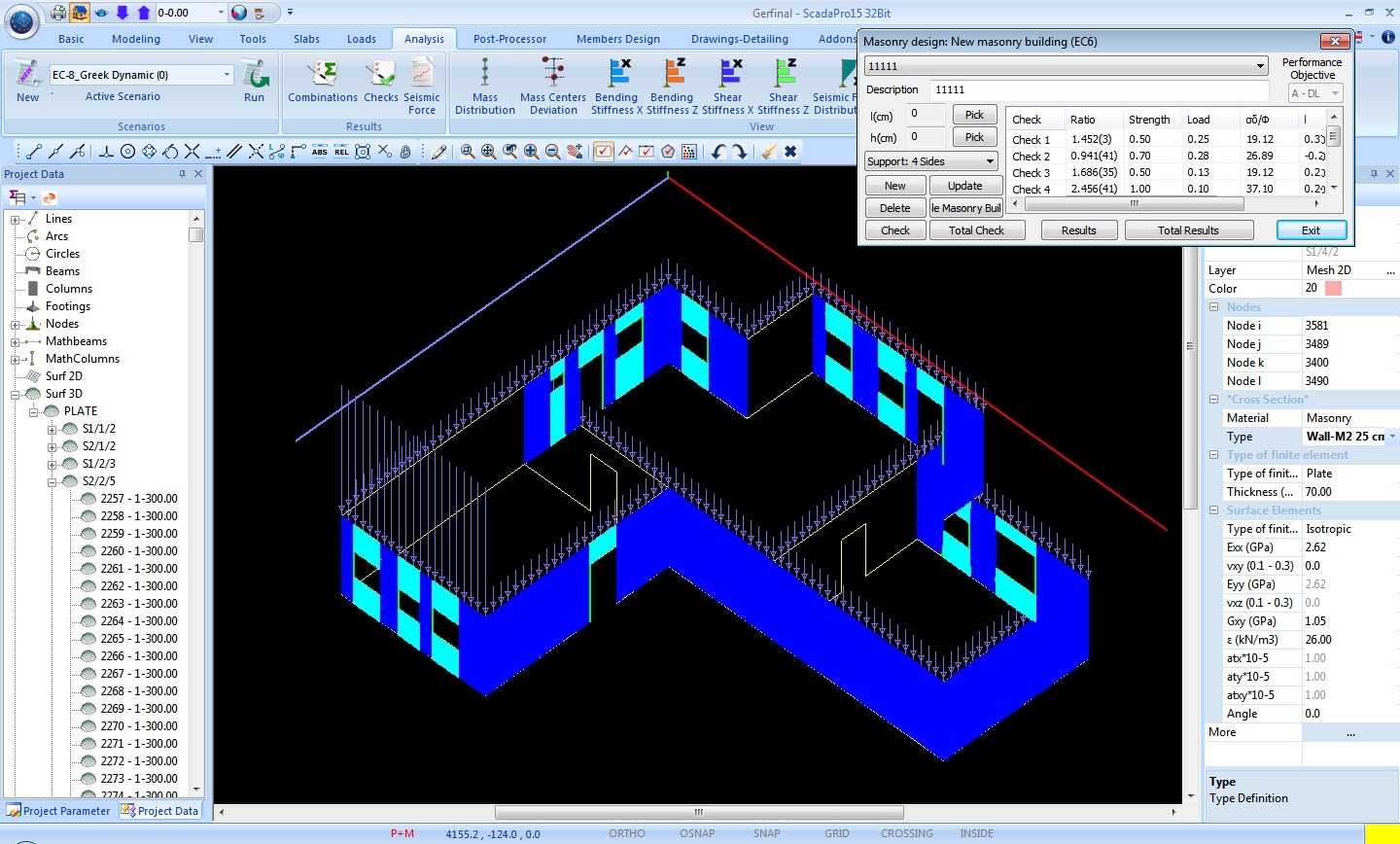
In SCADA Pro, any structure made of masonry may be modelled simply by defining the outline plan view, which can be done either by importing a .dwg or .dxf file or by sketching it manually.
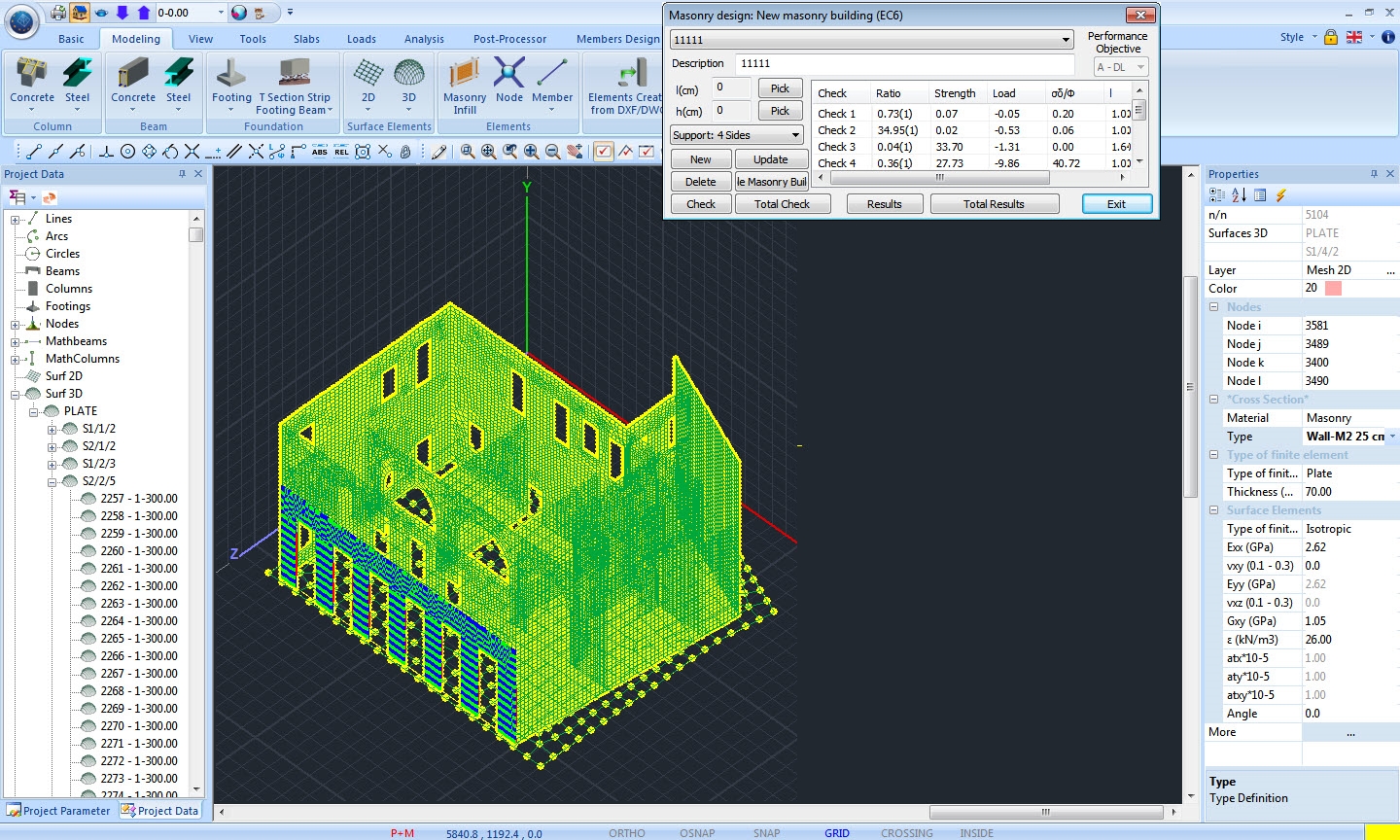
The finite element method is the most advanced approach to simulate these kind of structures.
The model is automatically generated by the use of 3D surface finite elements.
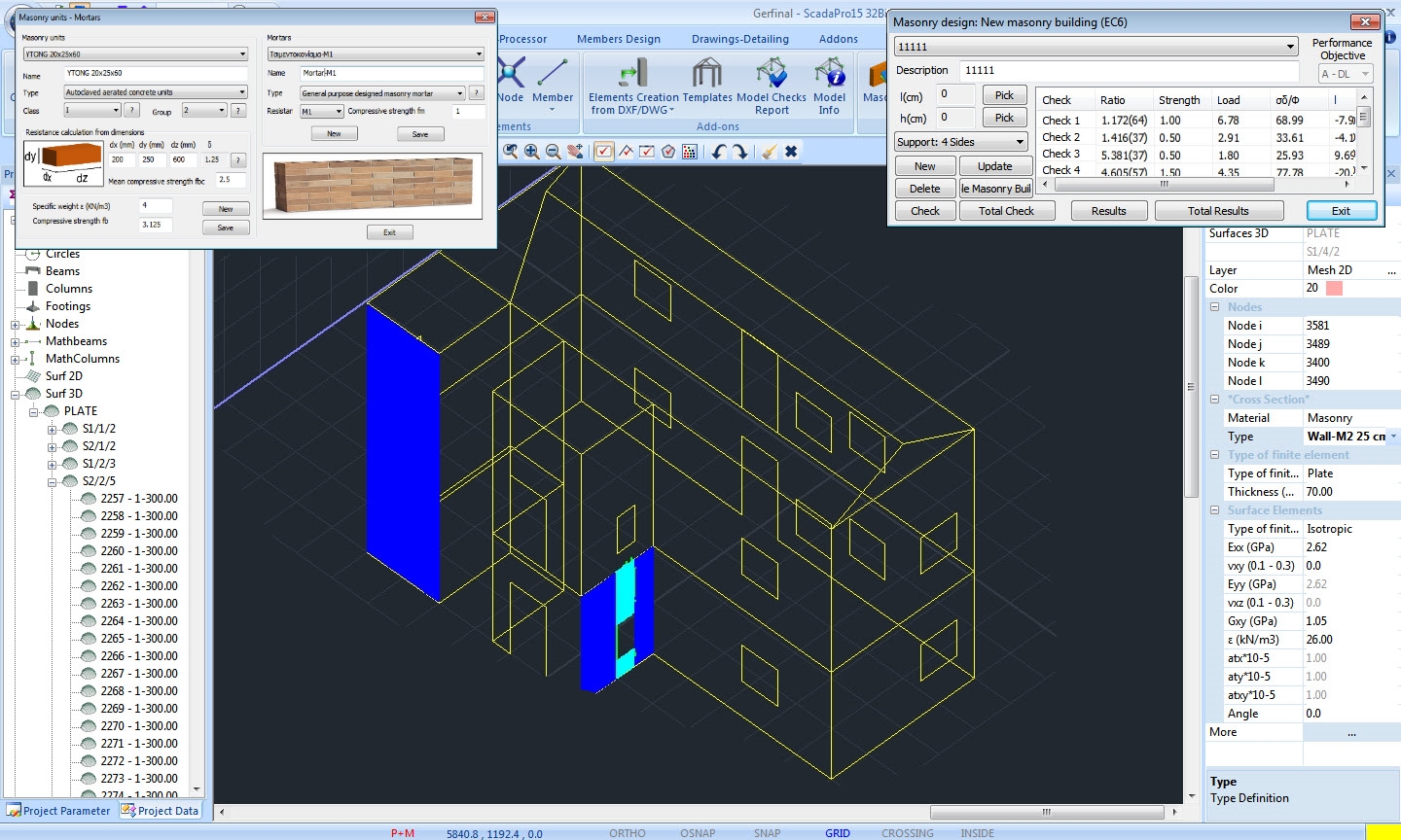
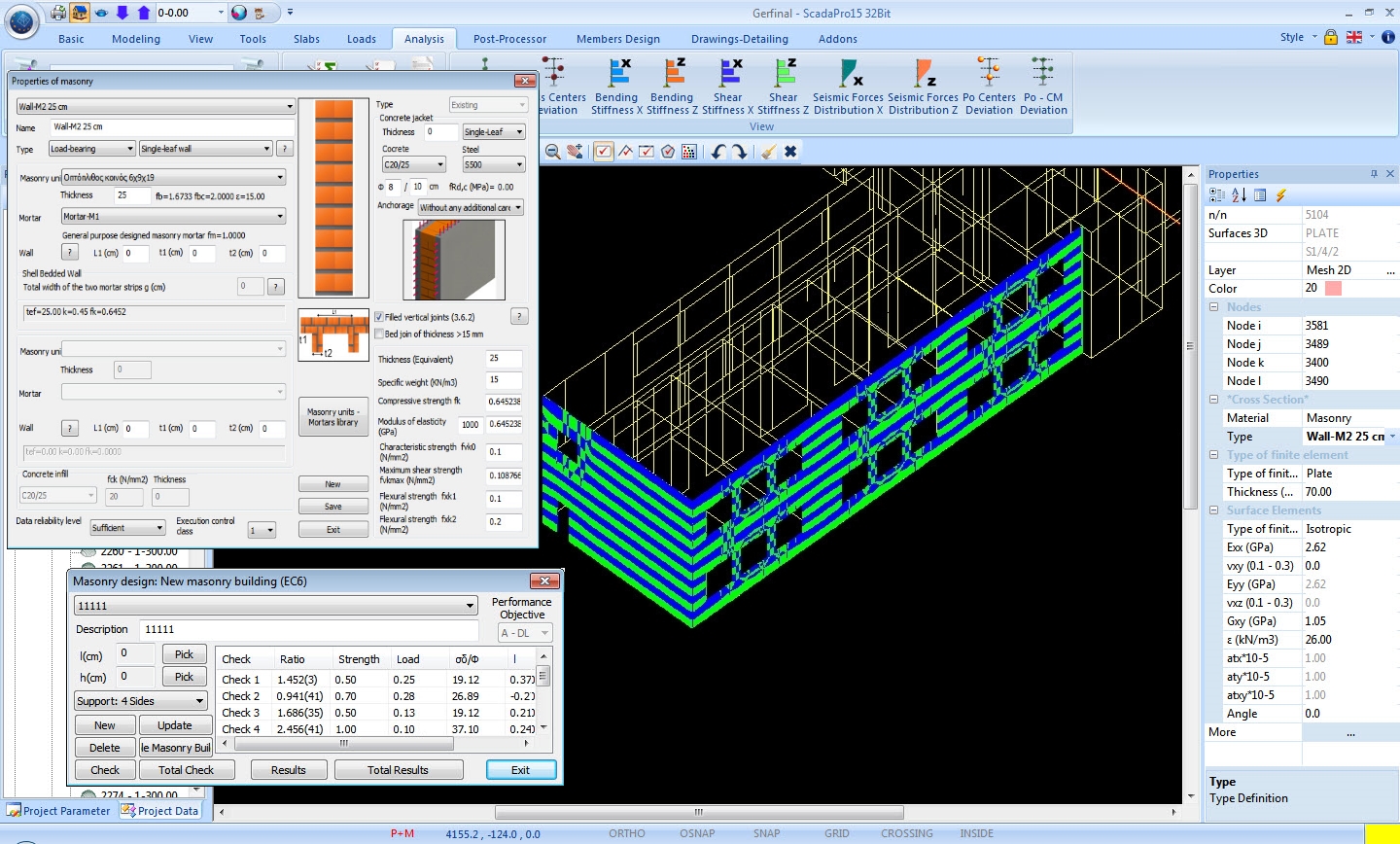
Then, through the rich library of wall types, masonry units and mortars available in SCADA Pro, the user can create the desired wall.
Linear finite elements may be present in the same model too, for the simulation of confined masonry.
As a result all kind of wall types, according to EC8 chapter 9 “Specific rules for masonry buildings” may be modelled, i.e.:
Unreinforced masonry,
Confined masonry,
Reinforced masonry.
SCADA Pro runs all the checks required by EC6 “Design of masonry structures”, namely:
In-plane bending check,
Out-of-plane bending check parallel to the horizontal joint,
Out-of-plane bending check perpendicular to the horizontal joint,
Shear check,
Vertical load check at the top, middle and base of the wall.
The user may choose to execute the above checks either at an entire wall or at a part of it according to his choice (e.g. a pier).
Presented next is a synopsis of the methodology for the design of loadbearing masonry structures, imposed by the relevant Eurocodes:
Eurocode 6 (EC6) – ΕΝ 1996-1-1:2005: Design of masonry structures
Eurocode 8 (EC8) – ΕΝ 1998-1:2004 – Chapter 9: Specific rules for masonry buildings
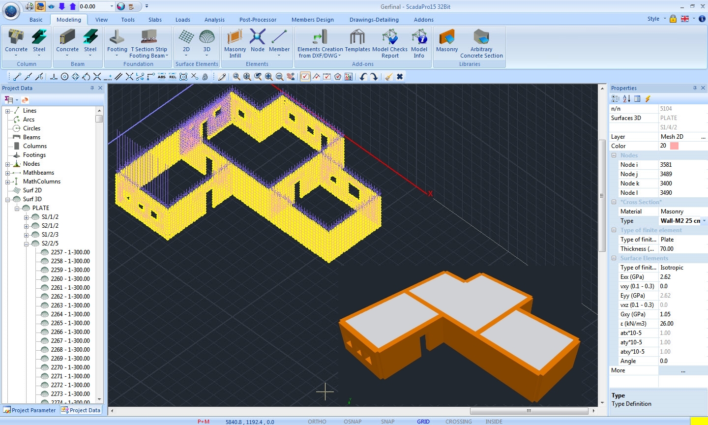
ΕΝ1996-1-1:2005 has been introduced for the design of loadbearing masonry structures.
Specific rules concerning the seismic design of masonry buildings are imposed by EΝ1998-1:2004 (chapter 9) and act supplementary to EC6.
Both these regulations have been incorporated in Scada Pro. A three-dimensional model of the masonry structure is created utilizing the finite element method. The walls are simulated with surface finite elements (shell elements).
SCADA Pro automatically rotates the analysis results into the two axes as instructed by EC6, i.e the one parallel to the horizontal joint of the wall and the other perpendicular to it.
Apart from the case of unreinforced masonry structures, there is also the ability to model a confined masonry building, using a combination of surface and linear finite elements in the same model.
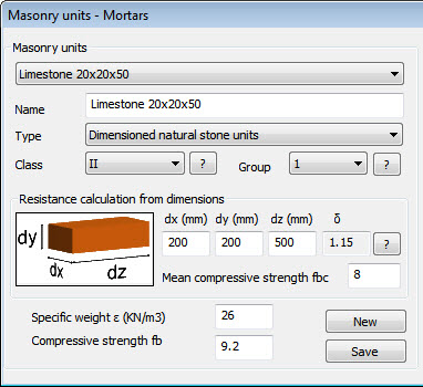
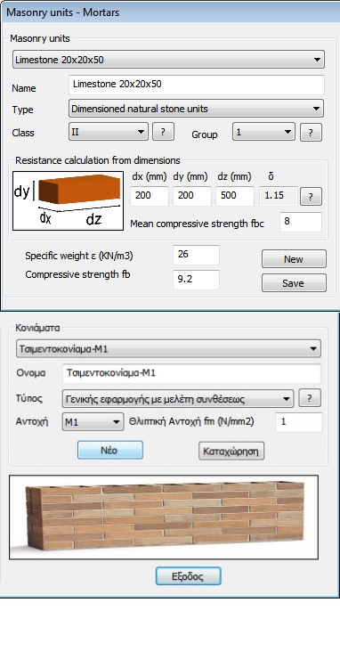
A rich library of masonry units and mortars is offered. Thus a great range of capabilities regarding their properties and ways of application is provided.
Masonry units made of:
Calcium Silicate,
Aggregate concrete,
Autoclaved aerated concrete,
Manufactured stone,
Dimensioned natural stone, of Category Ι or ΙΙ, and grouped in Group 1, 2, 3 or 4.
Mortars:
General purpose masonry mortar (designed),
General purpose masonry mortar (prescribed),
Thin layer masonry mortar,
Lightweight masonry mortar (of density 600 ≤ ρ ≤ 800 kg/m3),
Lightweight masonry mortar (of density 800 ≤ ρ ≤ 1300 kg/m3).
All types of masonry walls referred in the codes can be modelled.
Type of walls:
Single-leaf wall,
Cavity wall,
Double-leaf wall,
Grouted cavity wall (choice of type of concrete infill is provided),
Faced wall,
Shell bedded wall,
Veneer wall,
Wall stiffened by piers (geometrical properties determination according to EC6).
Additionally, the capability of strengthening a wall by the use of jacketing is also provided.
Jacketing parameters:
Single-leaf or double-leaf jacketing,
Type of concrete / reinforcing steel,
Geometric properties determination (i.e. thickness of the jackets, reinforcement ratios).
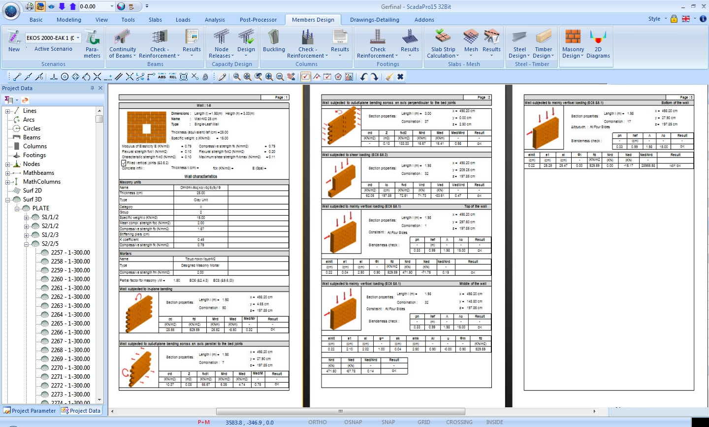
All the safety checks defined in EC6 use internal generalized forces (axial forces, shear forces and bending moments) instead of stresses.
SCADA Pro performs these checks in the similar manner.
The stresses computed in the finite element analysis are integrated on a section to derive the corresponding internal forces.
The user may define whatever section of a wall, horizontal or vertical, either for the whole length/height of a wall or for a part of it (e.g. for a pier).
Design checks:
Check of a wall under vertical loads,
at the top, middle and base of the wall.
Check of a wall under in-plane loading (other than vertical loading),
horizontal shear, bending moment (this check is not mentioned in EC6 but was a part of the design process described in the Greek Application Text (1995)).
Check of a wall under out-of-plane loading,
bending moment about an axis parallel to the horizontal joint of the wall,
bending moment about an axis perpendicular to the horizontal joint of the wall.
Rules for “Simple masonry buildings”
when satisfied all the aforementioned checks are not obligatory.
Assessment – Redesign (EC8, Part 3)
In SCADA Pro are implemented the provisions of EC8, Part 3 about the assessment of bearing masonry structures under seismic loading.
The design code recommendations are applied on masonry structural elements that resist against in-plane lateral forces.
The corresponding structural elements are the piers and the spandrels of a masonry wall.
The design checks are applied on the cross section of the pier/spandrel, where the dominant stress resultant is either:
The axial force and bending moment, or
The shear force
Consequently, the critical failure of the structural element is shown and the corresponding structural capacity is calculated for the three performance levels A, B, C.
Regarding the redesign, the reinforcing method of a masonry structural element is simulated by applying single or double leaf reinforced concrete jacket.
Έλεγχος σε κάμψη εκτός επιπέδου φέρουσας τοιχοποιίας
Ο έλεγχος εκτελείται για κάμψη περί οριζόντιο και περί κατακόρυφο άξονα και γίνεται τόσο σε όρους δυνάμεων όσο και σε όρους παραμορφώσεων.
Σε όρους δυνάμεων γίνεται με δύο μεθόδους
Με θεώρηση αδρανούς περιοχής
Με κλασσική θεώρηση της επαλληλίας των στερεών των τάσεων
Παρουσιάζονται αναλυτικά αποτελέσματα με τους λόγους επάρκειας ανά πεσσό και υπέρθυρο.
Στο μέρος του ανασχεδιασμού, προσομοιώνεται η ενίσχυση ενός υφιστάμενου στοιχείου τοιχοποιίας μέσω μονού ή διπλού μανδύα.
Ο μανδύας συμμετέχει στην αύξηση της θλιπτικής και διατμητικής αντοχής καθώς και στην εφελκυστική αντοχή μέσω του πλέγματος
Έχουν επίσης εισαχθεί στο πρόγραμμα μία σειρά τρόπων ενίσχυσης της φέρουσας τοιχοποιίας όπως:
Οπλισμένα επιχρίσματα
Ειδικά μεταλλικά προεντεταμένα στοιχεία με παραμετρικά χαρακτηριστικά για χρήση προϊόντων εμπορίου.
Ενέματα ομογενοποίησης.
Ινοπλισμένα πολυμερή (TRM) με παραμετρικά χαρακτηριστικά για χρήση προϊόντων εμπορίου.
Αντιμετώπιση εφελκυστικής αστοχίας και με τη χρήση των παραπάνω προεντεταμένων μεταλλικών ράβδων.
Για όλες τις παραπάνω μεθόδους και για κάθε μία χωριστά εκτυπώνονται αναλυτικά οι λόγοι επάρκειας με τα αντίστοιχα μεγέθη υπολογισμού τους.
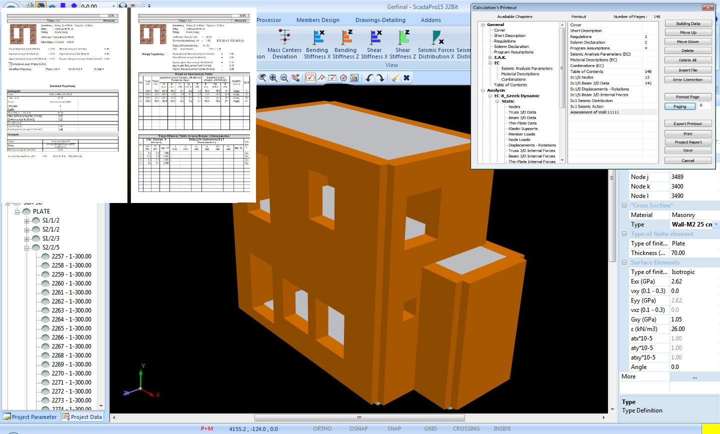
Report of the project
User friendly interface for the creation and editing of the report
In SCADA Pro the user simply selects the sections to be included in the report of the project.
Simple tools allow the user to edit the report header and footer position chapters and create automatically the table of contents.
Beams’ results also include envelope diagrams of internal forces.
The report may be previewed before the user can save it for further editing in one of the following file formats: RTF, PDF, HTML, PPTX, XLSX.
The results of the design of loadbearing masonry structures are also presented in a well-organized, format.
Accompanying drawings and other details are also available and included for better reporting.