SCADA Pro 16
ACE-HELLAS in the development and optimization of its products, in particular the application SCADA Pro, created the new version SCADA Pro 20016 with new upgraded features.
Parameters option added by starting a new project (Materials, Regulations, Steel Library)
When a new file is created, the General Parameter window is displayed in the interface enabling the user to set in advance parameters like the Material , the Regulation, the Project General Information and other parameters such as the Autosave time interval.
Detailed definition of these parameters can be found on subsequent chapters (Chapter 11 “Addons”).
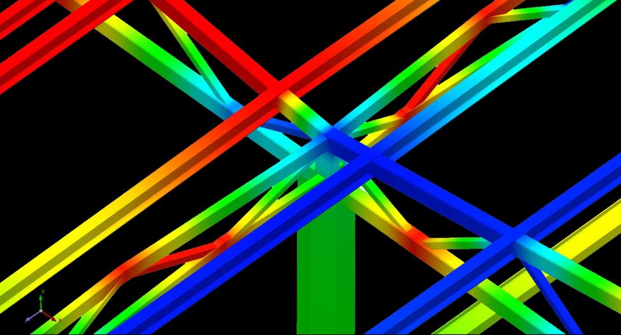
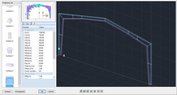
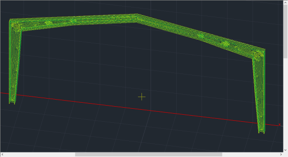
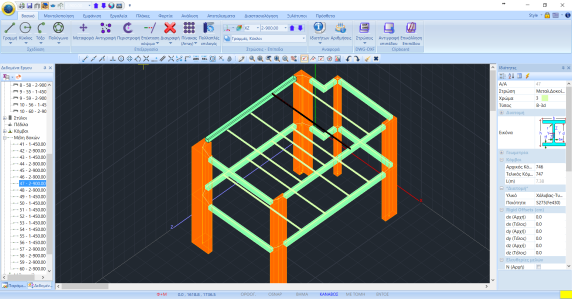
Added Automatic Simulation of typical steel variable-section frame by finite surface elements
It is also possible to simulate automatically typical metal variable-section frame with finite surface elements, defining the geometry and the respective thicknesses.
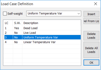
Added temperature variation load on finite surface elements
More specifically, for Plate (shell) elements added the uniform temperature variation load and the linear temperature variation load.
- The first (uniform temperature variation) causes membrane deformation in the plane of the element, while
- The second (linear temperature variation) causes deflection.
To note that the two loads of the plate element can be integrated either on the same loading, or in two different loadings.
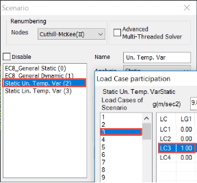
- Considering as two different loadings, to obtain individual results, each load MUST go to a different analysis scenario. The procedure to follow is:
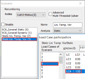
- Integrating both loads at the same analysis scenario, you will get aggregated results in one load (the first).
For Plane elements (Stress, Strain, Axisymmetric) only Uniform Temperature Variation is possible.
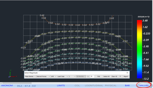
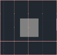
Added the possibility of displaying the selected values inside the surface of the surface element
Activating the prices in the lower horizontal bar, you can see the values of the selected size in the surface of the surface element.
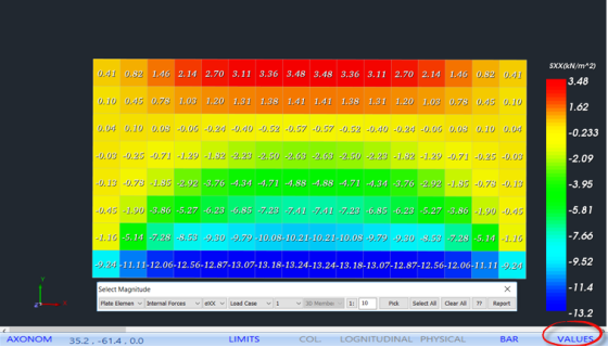
And also the value of the Stress Contours over them
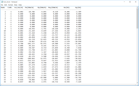
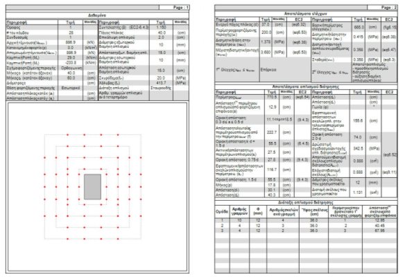
Added Report command for the reinforcement of the surface elements
It concerns the reinforcement of the surface elements
![]()
Selecting it, displays for each surface element:
- the worst As,
- the combination that comes for and
- the corresponding intensive forces.
There is the possibility of printing the results either globally for all elements, or for the elements of the subgroup or subgroups selected.
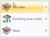
Added modeling and designing of flat slabs
![]()
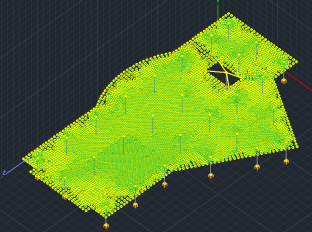
The new version of SCADA Pro offers the possibility of creating flat slabs (slabs without the presence of beams) with the finite element method.
The procedure for the modeling of flat slabs requires:
- the 3D Mesh definition,
- the External Boundary creation ,
- the Holes automatically creation in place of the Columns,
- the Mesh calculation and the mathematical model calculation.
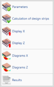
The command “Flat slabs” includes the commands:
- Parameters
![]()
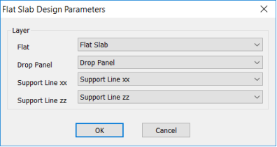
In the dialog box you define the correlation between Layers.
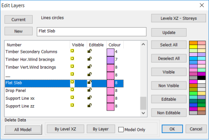
The default Layer’s list of Scada includes the layers related to the flat slabs.
- In “Flat Slab” layer transfer the outline of the slab and correspond it to the Layer “Flat”.
- In “Drop Panel” layer transfer the Lines that define the area around the columns, where will increase the thickness of the slab locally. The “Drop Panels” are inserted optionally around the columns of the slab relieving the fatigue from drilling.
- In “Support Lines xx” and “Support Lines zz” transfer the Lines that define the Support Lines. These are lines insert in both X and Z directions between successive points of the slab. Usually connect column’s nodes and end on the outline of the slab.
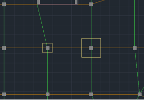 Drop Panels and Support Lines
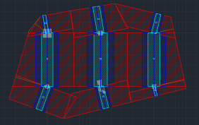
- Based on the designed Support Lines will be generate the corresponding Design Strips.
- Calculation of design strips
![]()
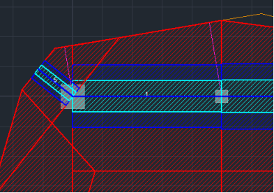
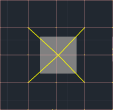
According to Annex I of EC2 flat slab is divided into design strips. These are the areas that are automatically created by the program on both sides of the Support Line, according to Figure I.1 of EC2.
Select the command Calculation of design strips and the program automatically creates them.
Each Design Strip is divided into sections along its length perpendicular to the Support Line. In each section Scada integrates the internal forces of finite surface elements intersect. By completing this occur the bending moment around the axis of the section. This intensive value used to calculate the armature in each section.
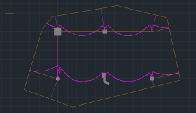
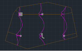
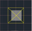
- Display Χ, Ζ
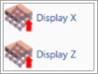
Select to display the Design Strips in both directions.
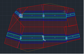
Design Strips along the X and Z axes
- Diagrams Χ, Ζ
Select Diagrams in both directions to see the corresponding diagrams.
- Results
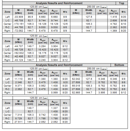
![]() This command opens the Results file through the Report.
This command opens the Results file through the Report.
Each page concerns a Strip Line.
Initially described the characteristics of the Strip.
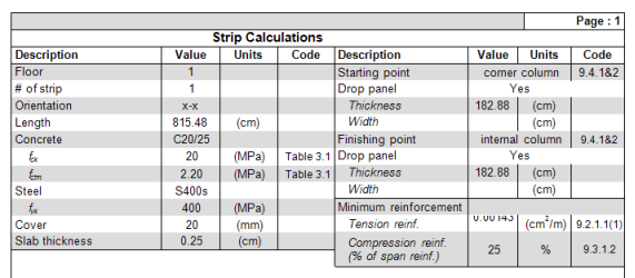
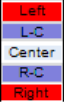
Then displayed the reinforcement results above and below in detail for each zone, dividing them into sub-zones.
– Left-Right -> red zone
– L-C R-C-> blu zone
– Center-> light blue zone
Punching checks
Added in the new version also the punching checks in accordance with EC2. The check is part of the check and design process of the flat slabs which runs automatically, but can also run as an individual check for any column. All data can be set automatically or even manually.
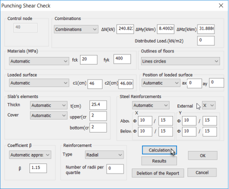
•Production of complete results print out, with detailed reinforcement layout plan (radial or cross), whenever required.
•Details designing.
Added library of steel sections according AISC (Shapes Database)
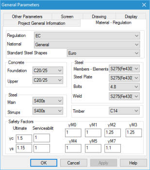
- Materials – Regulations
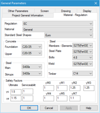
When a new file is created, the General Parameter window is displayed in the interface enabling the user to set in advance parameters like the Material, the Regulation, the Project General Information and other parameters such as the Autosave time interval.
Added library of steel sections according AISC (Shapes Database)
Furthermore, you can set and the desired safety coefficients γc, γs, γΜi with i=0-7
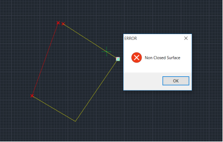
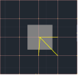
Automatic fault detection during the surface closed contour defining
The program provides automatic fault detection during the surface closed contour defining and displays a red cross points where the selected contour is not closed.
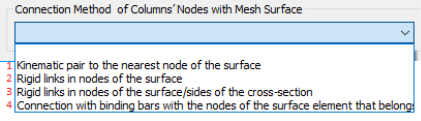
New connection mode selection possibility of columns with surface plates (superstructure, raft)
SCADA Pro allows the combination of linear and surface elements in the same project. The new version contains new connection methods of linear elements with surface. On the bottom part of the window the user may select the connection method between the nodes of the columns and the surface mesh. Four methods are available using kinematic constraints or connecting elements.
|
1 |
2 |
3 |
4 |
|
|
|
|
|
Select the level, the type of connection and press Execute.
Separation of extend and trim commands for easier use
Extend–Trim : Commands to expand or cut an object up to a limit that you specify.
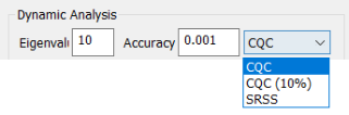
Added new possibility of choosing the combination of modal responses
There is also the possibility of choosing the combination of modal responses according CQC, CQC(10%), or SRSS.
Two-way communication with the programs SAP2000 and ETABS
The new bi-directional communication of SAP2000 and ETABS with SCADA Pro, allows exporting and importing of any project in SCADA Pro offering the possibility of designing projects of reinforced concrete, steel, masonry and wood using the corresponding Eurocodes and National Appendices.
This version gives the possibility, using intensive forces derived from the analysis of SAP2000 or ETABS, to make the design of the structure according to Eurocodes and Arab Regulation (SBC), something that absolutely limited in SAP2000 or ETABS.
Specifically, in SCADA Pro there are the following possibilities:
- Automatic slab recognition, loads import and resolution, which cannot be done in SAP2000 or ETABS.
- Possibility of displaying the deformed model for each combination, each load or eigenvalue.
- InSCADA Pro ispossibletodesigntheprojectusingeachregulation(EC2, EC3, EC5, EC6, EC8(3), SBC).
- Possibility of editing the reinforcement inside the editors, receiving structural designs, details, continuity of beams and columns and complete print out.
- Optionally, includes also checks which cannot be done in SAP2000 or ETABS (ex. Punching checks)
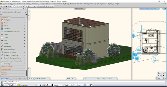
Communication between Scada - Archline
SCADA Pro combines the advanced algorithms with the powerful capabilities of ARCHline.XP, a great program for architectural design and rendering.
ARCHline.XP based on BIM technology, which helps the engineer to visualize, evaluate and communicate his project more effectively. All components are stored in a central database, including information on their geometry and physical structure.
The xml files exported by ARCHline.XP provide accurate data which allow the automatic identification of all the components of the Scada Pro: columns, beams, foundation elements and loads.
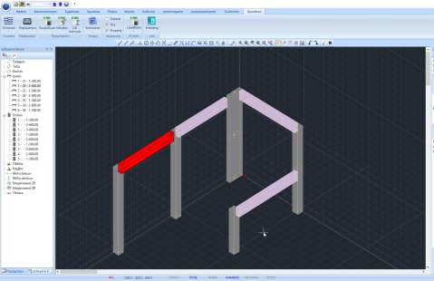
New command for merging broken beams
In the new version added the command for merging broken beams. Where the beams include surface elements is a need to break the members of the beams in order to ensure the necessary connections between the linear and surface elements.
New possibility of inserting beams and columns as physical section in the 3D representation.
Now there is the possibility to insert a physical element (beam, column) directly as a 3D element, even without its mathematical element.
Use the attraction points in the grid to start inserting them and connect them easily with elements in different levels.
New optimized analysis algorithms
The program is now integrated new rapid analysis algorithms, using more resources, such as the graphic card, resulting in their more rapid implementation (Parallel Processing). The activation is done through the creation of scenarios:

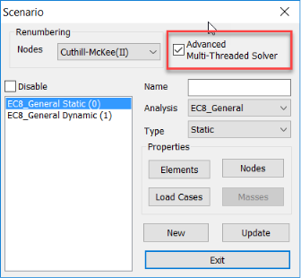
By choosing this solver, the time of the analysis execution reduced, depending on the size of the project, up to 500%!
Extra features - additions - improvements
- Recognition of additional sections in dwg (Π with edges etc.)
- Integration of Polish regulations by adjusting all the relevant parameters
- Member’s length displays in the table of properties.
- Messages during the mathematical model creation
- Definition of the 3d surface external border and holes by the selection of the first line of the closed contour, provided however that no branching
- The layer of dwg file imported Scada Pro now sorted alphabetically
- It is no longer possible to import levels with the same height and cannot introduce double column in the same place.
- Local cross-section axes now appear also in columns detailing