Introduction, modeling and structural analysis
SCADA Pro Analysis +
Application for static and dynamic analysis of structures, for reinforced concrete, steel, timber and masonry
Detailed Description
SCADA Pro Analysis is a complete and comprehensive application for static and dynamic analysis of structures, for reinforced concrete, steel, timber and masonry, according to Eurocodes and most European National Annexes. SCADA Pro includes also, the National Building Codes of Greece (EAK), Italy (NTC2008), Poland (LGOM) and Saudi (SBC).
Interface
New interface for even more flexibility and productivity
Invest and learn a single application that will meet all your needs for the analysis and design of any structural project with different materials.
SCADA Pro, based on Microsoft Ribbon technology, offers a unified, innovative and beautiful user interface, where it is easier to use more commands in a fully customizable environment.
Ribbons allow the visual arrangement and grouping of the commands in order to enable the user to discover and use the application’s tools easier, faster, and more efficiently.
On the left side of the interface, there is the navigation tree that includes the entire model’s data for easy finding and editing, categorized either per storey (level) or per type. It provides a detailed overview of the project and quick search and access of the data interacting with the visual model and the corresponding properties on the right side of the screen.
When the storey list is active, select an element from the storey list, occurs the isolation of the elements of that storey, making invisible the rest of the project and easier to localize the selected element.
Furthermore, a list of optional commands appears when right clicking, that helps user to find features fast.
Ταυτόχρονα απομονώνεται η στάθμη στην οποία ανήκει , ενώ στη δεξιά πλευρά της οθόνης εμφανίζονται οι ιδιότητές του με δυνατότητα άμεσης τροποποίησής τους.
Η κατηγοριοποίηση αυτή επιτρέπει τον εύκολο εντοπισμό οποιουδήποτε στοιχείου και με την επιλογή του από το δέντρο εμφανίζεται με διαφορετικό χρώμα στο φορέα.
Η λειτουργία αυτή μπορεί να εκτελεστεί αμφίδρομα δηλαδή να γίνει η επιλογή γραφικά πάνω στο φορέα και αυτόματα να εμφανιστεί το στοιχείο στο δέντρο με τις ιδιότητές του δεξιά της οθόνης.
Επίσης υπάρχει δυνατότητα εφαρμογής συγκεκριμένων εντολών σε κάθε στοιχείο του δέντρου που επιλέγεται.
Η εμφάνιση του μενού των εντολών γίνεται με το δεξιό πλήκτρο του ποντικιού και το μενού αυτό αλλάζει ανάλογα με την ενότητα του προγράμματος που είναι ενεργή.
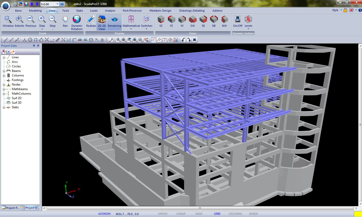
Modelling
Automatic recognition of cross sections and creation of the structural model from a .dxf or .dwg file. Minimizing time for data input.
Ο χρόνος εισαγωγής των στοιχείων του φορέα σας ελαχιστοποιείται.
Γίνεται επίσης αυτόματα η αναγνώριση των πλακών του φορέα καθώς και των προβόλων που έχουν σχεδιαστεί με απλές γραμμές.
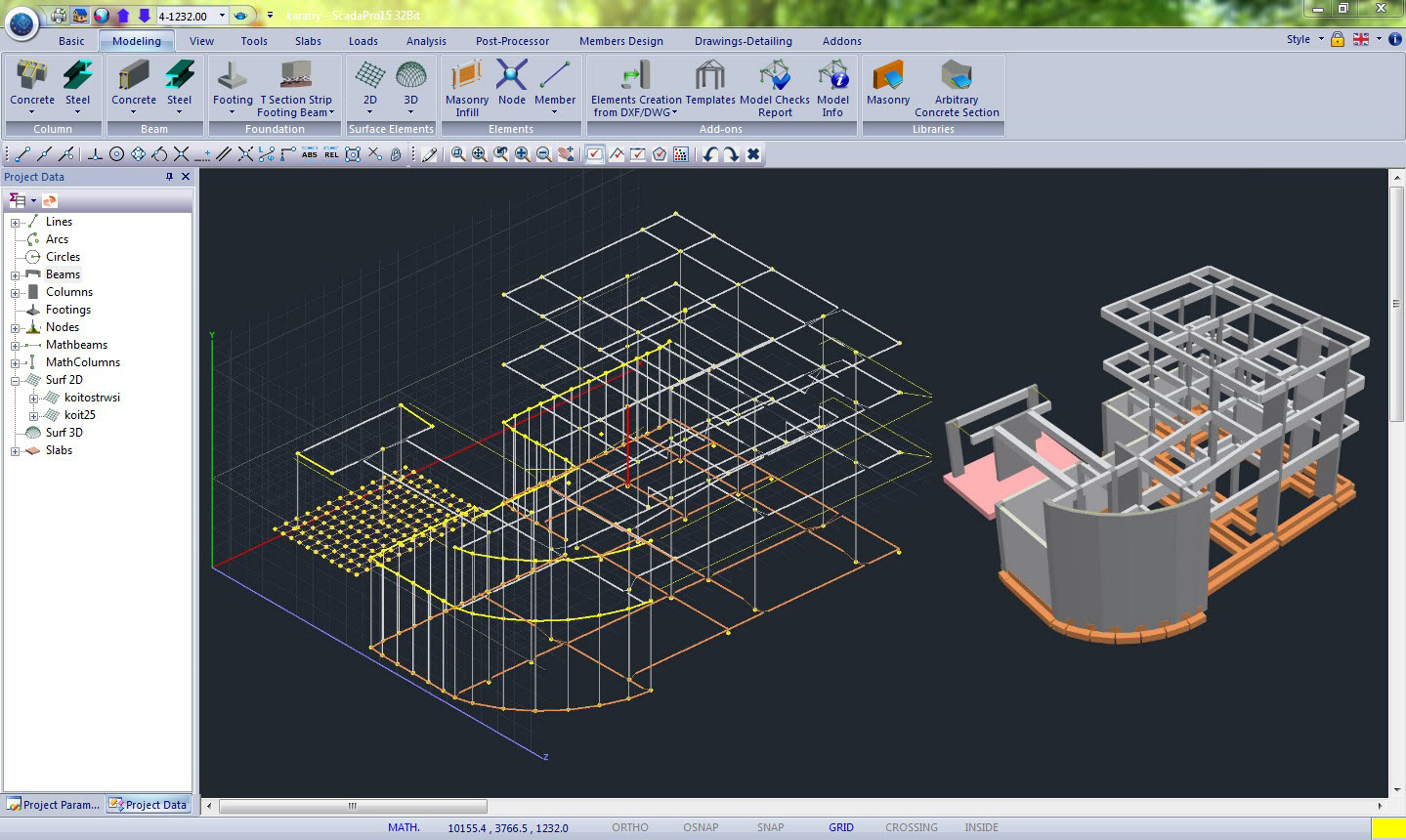
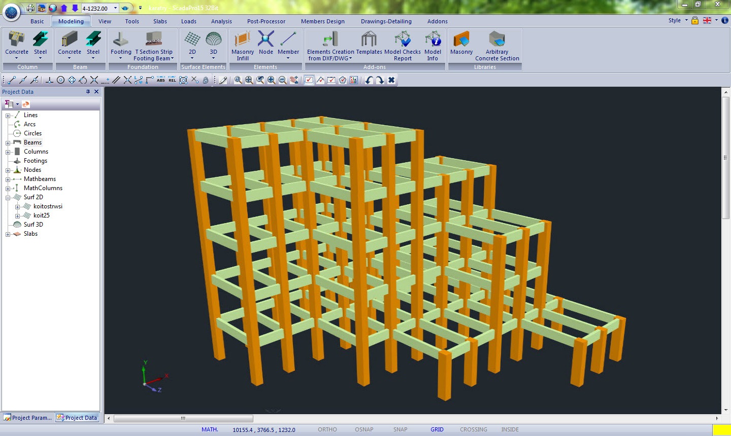
Using the innovative interface of SCADA Pro it is easy to recognize and create the physical model of the structure out of any architectural drawing using .dxf or .dwg format.
The recognition and simulation process of the cross sections located in the library of SCADA Pro is performed selectively or automatically per storey, per structural element (columns, beams, slab, foundation connecting beams) and in total for the whole structure. Automatically the three-dimensional physical and mathematical model of the structure is created.
Also, the recognition of the structural slabs and cantilevers that are defined with simple lines is performed automatically.
Complete compatibility between AutoCAD Revit Structure Suite and SCADA Pro
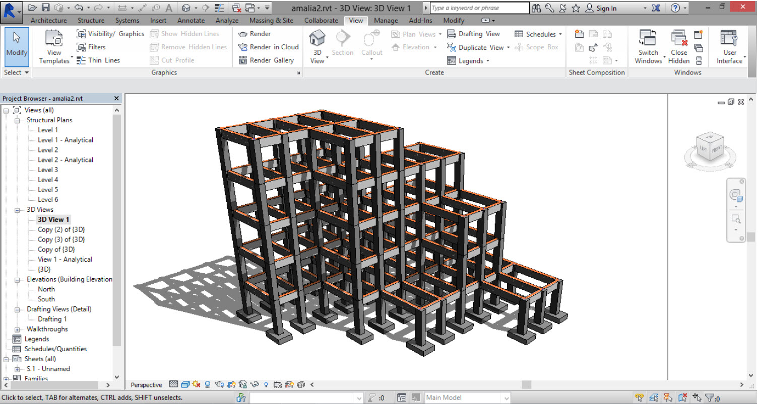
AutoCAD Revit Structure Suite a full set of applications in order to create structural models.
The two-way connection to SCADA Pro offers an easy way to import 3D architectural models ready to be analyzed.
All structural elements, columns, beams etc., as well as the loads and steel connections are transferred automatically and accurately to the mathematical model of SCADA Pro.
Bidirectional communication between architectural and structural models ensures time savings and cost reduction.
SCADA Pro is certified by Autodesk for the automatic, bi-directional communication with the Revit Structure.
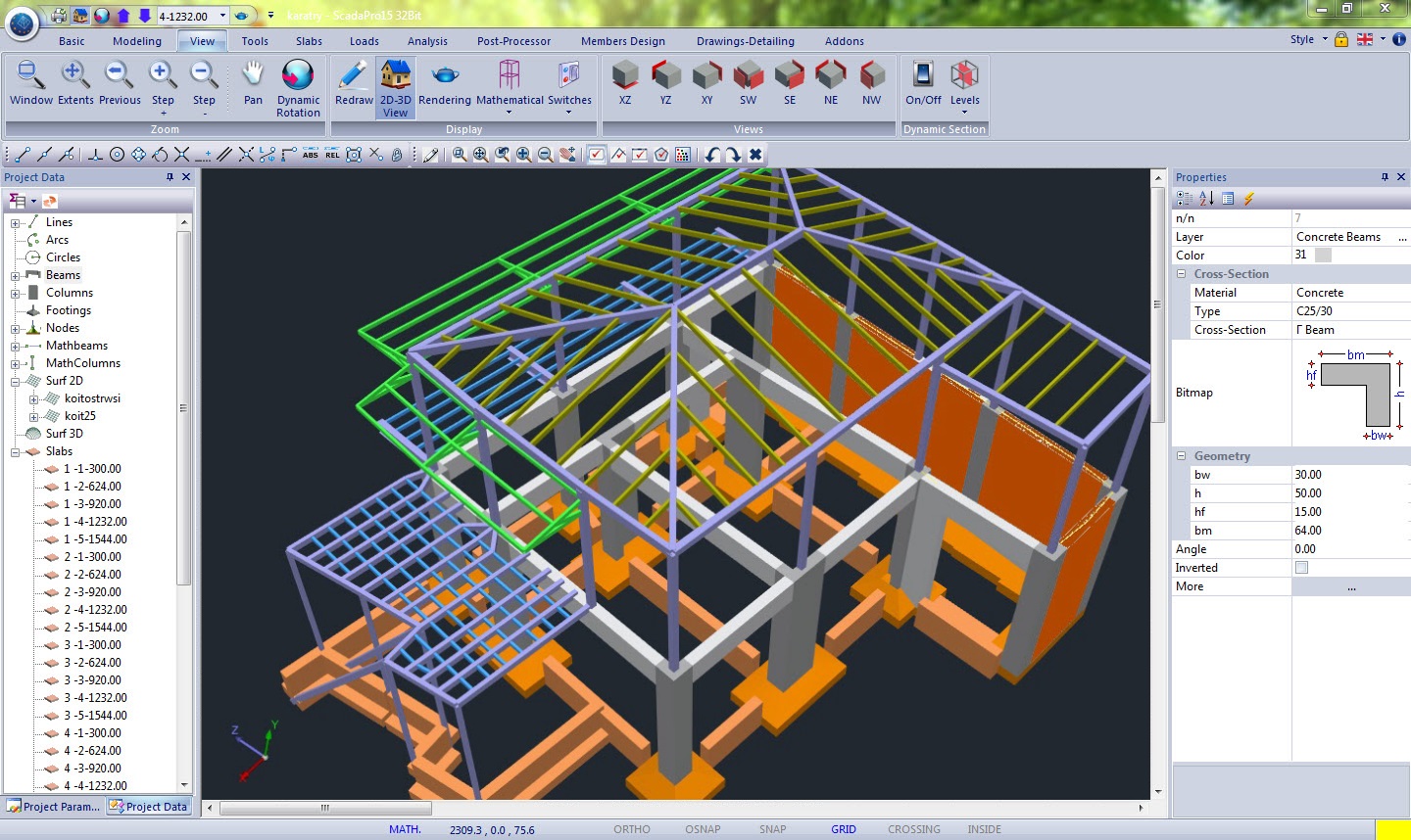
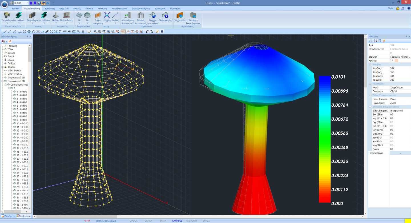
3D FEM
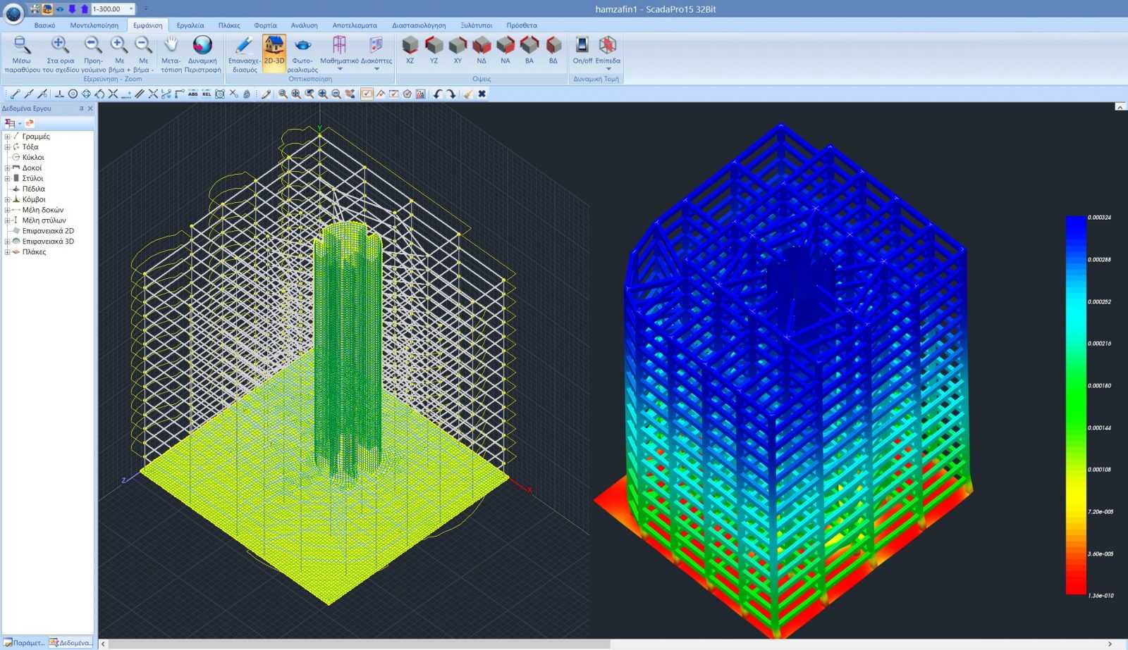
New powerful mesh generator of 3D surface finite elements
Στην νέα έκδοση του SCADA Pro έχει ενσωματωθεί μία νέα γεννήτρια 3d πεπερασμένων επιφανειακών στοιχείων στο χώρο, με δυνατότητα προσομοίωσης επιφανειών οποιασδήποτε γεωμετρίας και σχήματος με οπές και σημεία συγκέντρωσης τάσεων (πυκνώσεις πλέγματος στοιχείων).
Η δημιουργία του πλέγματος γίνεται αυτόματα με ταυτόχρονη ταύτιση κόμβων ραβδωτών και επιφανειακών στοιχείων. Τα αποτελέσματα για τα εντατικά και τα παραμορφωσιακά μεγέθη καθώς και για τον υπολογιζόμενο οπλισμό As εμφανίζονται με τη μορφή ισοτασικών καμπυλών.
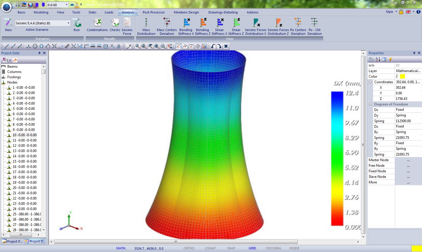
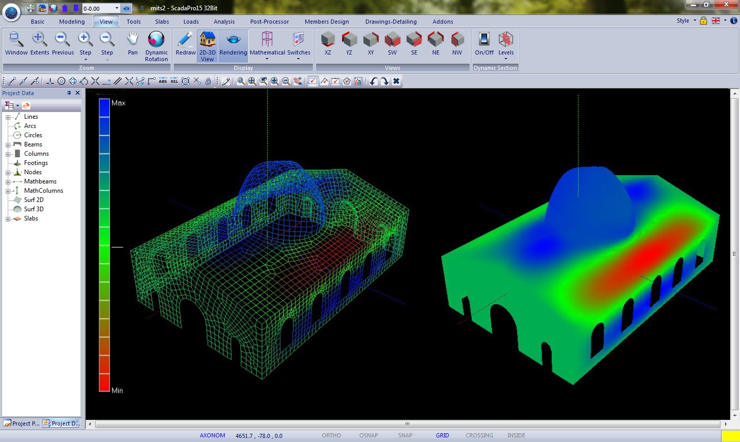
A new mesh generator of surface finite elements is provided in SCADA Pro.
Surfaces of any shape may be modelled. Easy meshing no matter what the pattern of holes or stress concentration points are.
The mesh generation is automatic even when both surface and linear elements are present (nodes of neighboring linear and surface elements are automatically merged together).
The ability of inserting a point for adaptation of the mesh around it is also available.
The program also allows the insertion of a hole in an already meshed surface.
Any kind of material may be attributed to a mesh with no problem.
Contours concerning the stress resultants, the strains or the computed reinforcement percentage As may be drawn on the produced mesh.
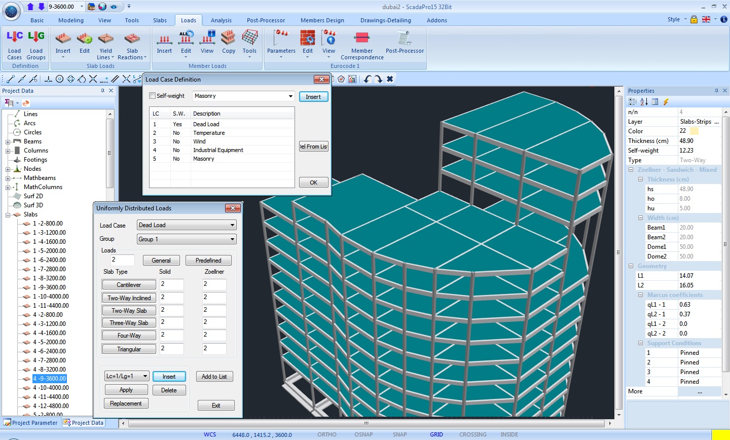
Loads
Input loads for the structure: Direct load definition on members using any type of load.
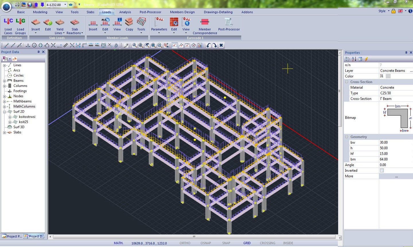
SCADA Pro gives the user the option to input graphically, on members, any type of load.
All load types are supported, e.g. uniformly distributed forces, concentrated forces, nodal forces, torsional moments, settlement, thermal actions etc.
Loading and combinations required by EC 0 are automatically calculated, with full editing options for the user.
Automatic generation of wind and snow loads according to EC1 and SBC301, as well as automatic attribution to the members with respective generation of load cases, ready for analysis.
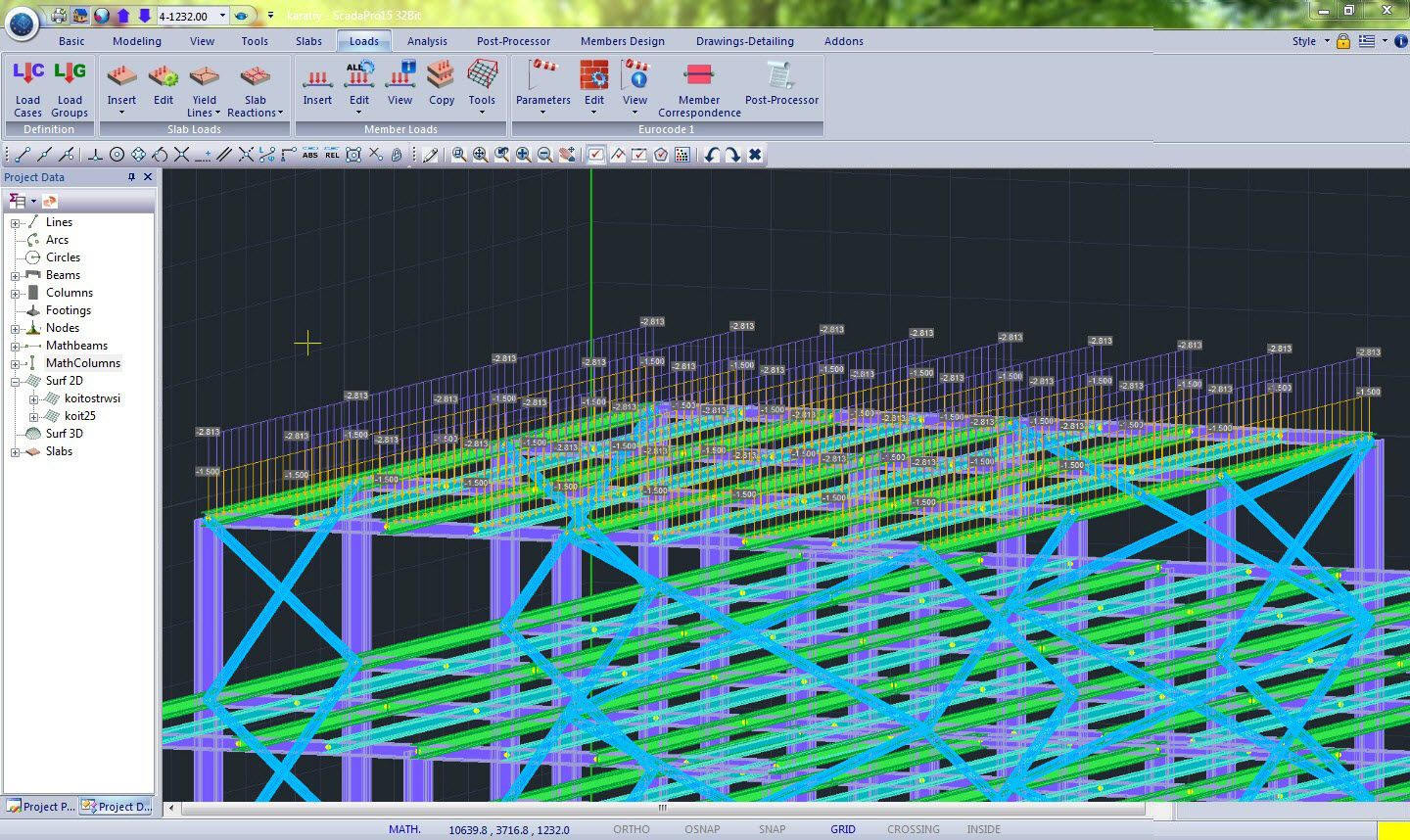
Self-weight is automatically calculated and may be optionally excluded in the analysis. Distribution of load on a 2D or 3D Mesh surface is also automatic.
User may always visualize the loads attribution using the three-dimensional display, of the load of the structure, on the respective members.
Messages display for potential errors, in model geometry of structure and the loads of beams and columns, are also available.
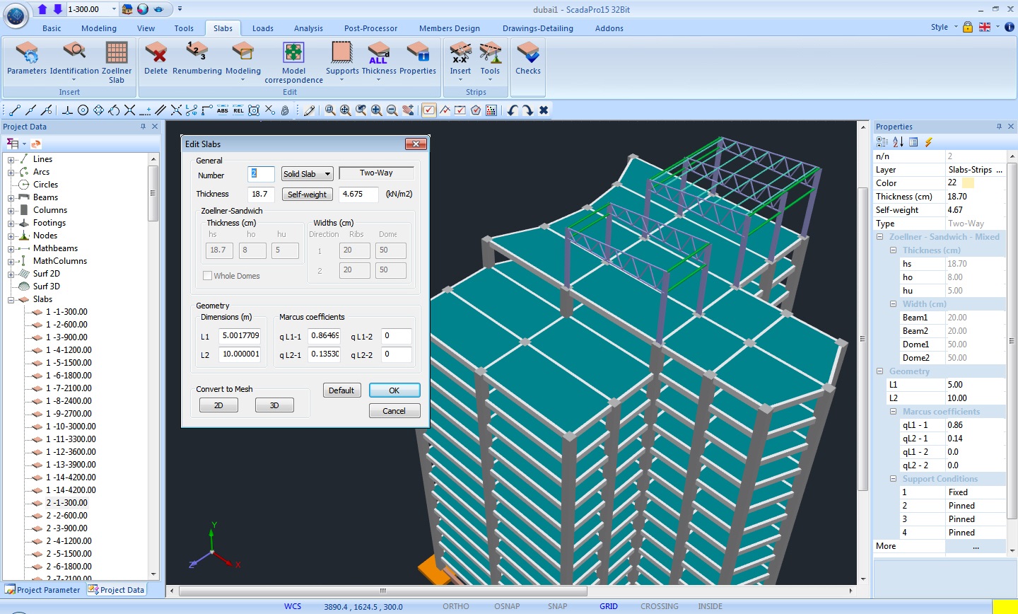
Input of slabs and slab loads
The identifications of the slabs in SCADA Pro is automatic, such as their respective support conditions.
Η αναγνώριση των πλακών στο SCADA Pro γίνεται αυτόματα με αυτόματο προσδιορισμό των συνθηκών στήριξής τους.
Slabs of any shape and any type are considered (Conventional, Zoellner, Sandwich).
Display of yield lines and automatic attribution of slab loads to the respective bearing beams, calculated through Marcus coefficient method according to the slab’s support conditions.
There is also available the feature of converting a conventional slab to a slab simulated with finite surface elements.
The minimum thickness of the slab is calculated automatically based on control of slenderness
The loads on the slabs can be applied to all slabs or selectively with instant processing and editing.
Μπορούν να εισαχθούν φορτία ομοιόμορφα γραμμικά ή τμηματικά.
Η απόδοση των φορτίων γίνεται με ένα κλικ στους στύλους και της δοκούς έδρασης με αντίστοιχη εμφάνιση των γραμμών διαρροής και των επιφανειών επιρροής ανά μέλος.
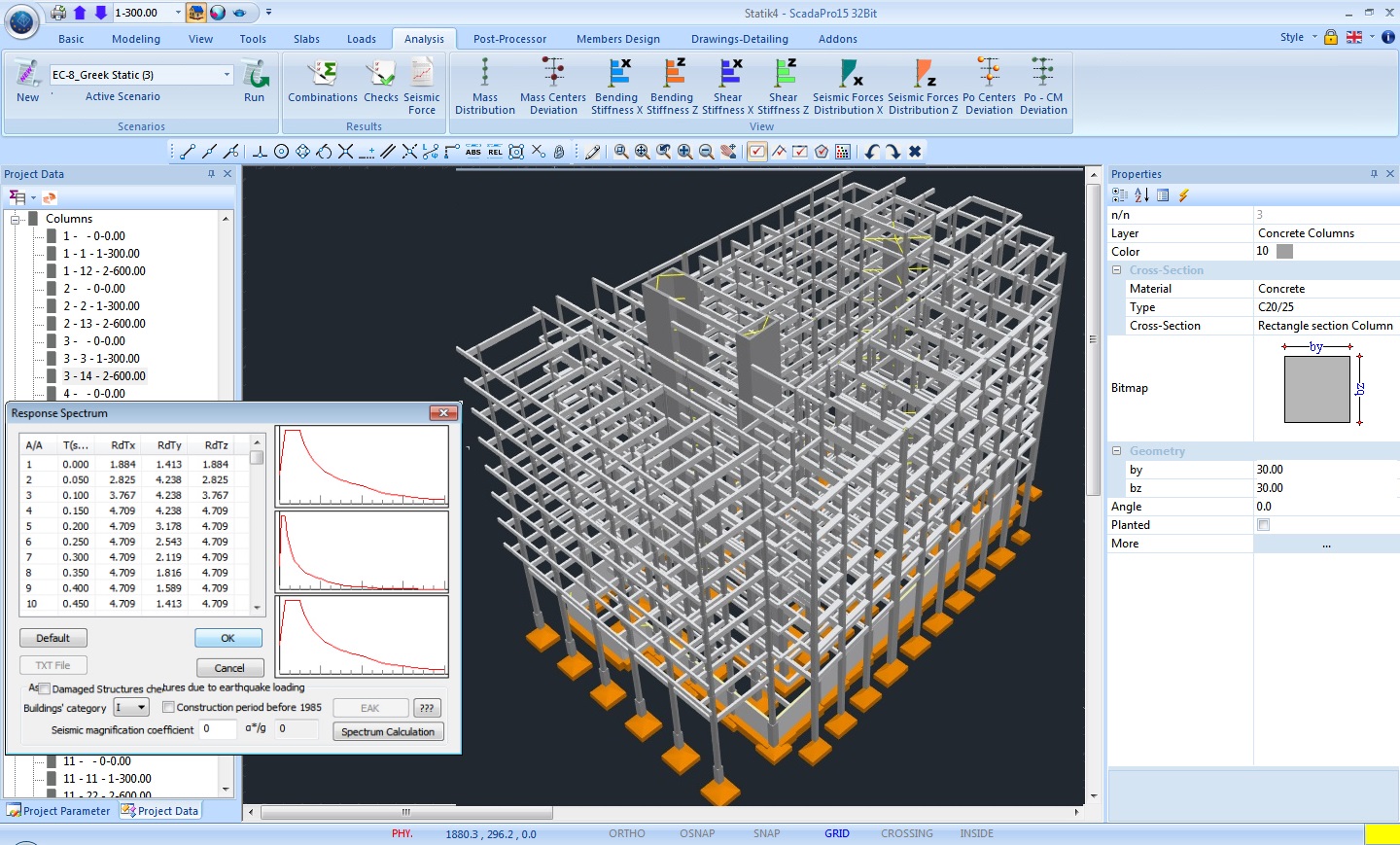
Analysis Types
Fast and reliable solvers so that the user can rely on
SCADA Pro incorporates more than 30 years of know-how from ACE-Hellas advanced research and development team.
It uses the most powerful solvers for all analysis methods and advanced parallel processing components to minimize execution time.
The following analysis methods are included:
Linear Simplified Spectral Method (Equivalent Spectral Method)
The linear simplified spectral method refers to the calculation of the displacements, deformations and the internal forces of the structure under static loads.
The calculation of the response is carried out by solving the linear system of equations that describes the model of the structure.
The externally imposed loads can be point on the nodes or distributed along the members, while the self-weight of the structure is taken into account.
The results of the linear static method can be used for the design of the structure, using the parameters provided by each regulation.
Linear Dynamic Spectral Method
The linear dynamic spectral method is a simplified approximate analysis method, which uses superposition of the eigenmodes for the estimation of the maximum response of the structure, under earthquake excitation.
Using this methodology the complete calculation of the response time histories, required in dynamic analyses, is avoided.
Instead, the spectral values of the response that correspond to each eigenmode are calculated.
The value of the maximum response is next estimated using statistical analysis, since the maximum response of each eigenmode does not occur on the same time, but also the exact time is not known.
The great advantage of the spectral dynamic method is the fact that it requires a reduced amount of eigenmodes for the estimation of the structure’s response and therefore reduced computational cost.
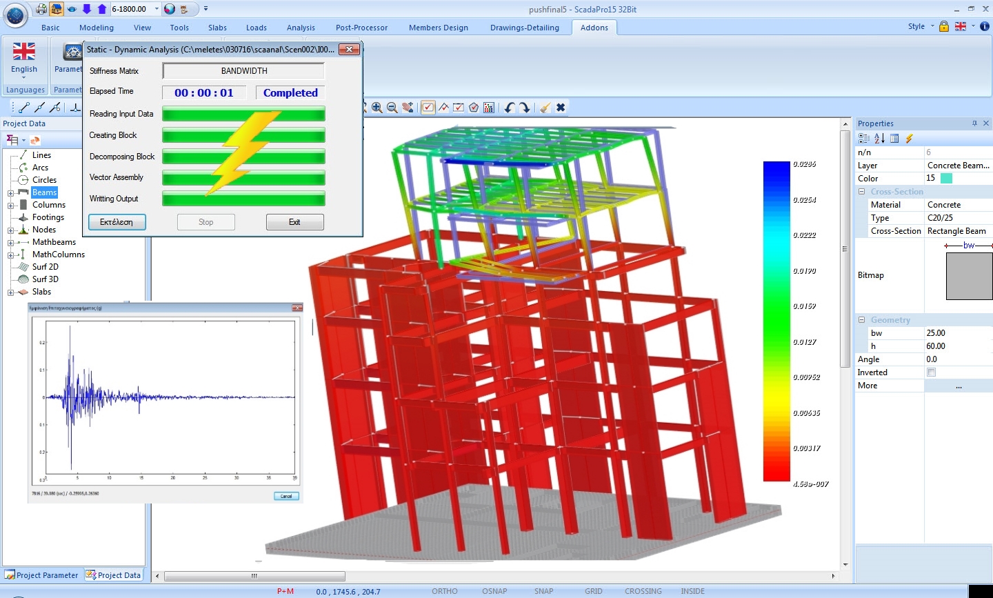
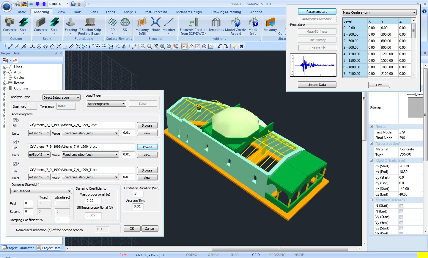
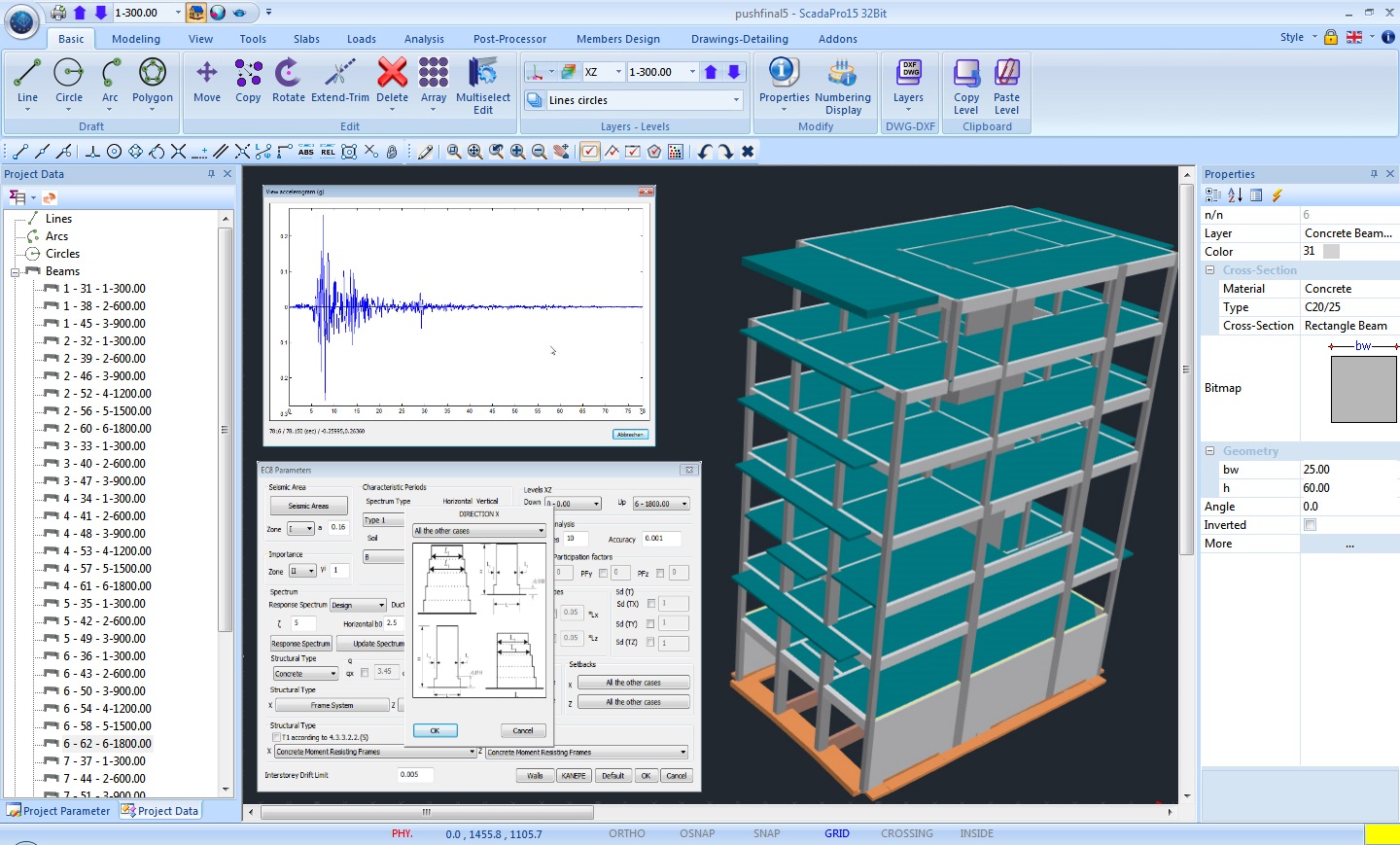
Linear Dynamic Time History Analysis
Time history dynamic analysis refers to the calculation of the structure’s response under a predefined external load that varies in time (earthquake excitation).
Time history dynamic analysis is divided into linear and nonlinear.
It is considered as linear when all the structural members behave elastically and therefore the structure responds linearly to the imposed loads.
For the calculation of the response, the structural equations of motion have to be solved.
This can be done in two ways: modal analysis or direct integration of the equations of motion.
As far as the modal analysis is concerned, a reduced amount of eigenmodes that contribute to the response are chosen.
Normally, a quite small amount of eigenmodes with respect to the total degrees of freedom of the model, can lead to a satisfactory estimation of the time history response.
This leads to an important decrease of the computational cost.
As far as the direct integration method is concerned, the full mass, damping and stiffness matrices are used at the equations of motion, which are numerically integrated with respect to time.
The computational cost increases, but the solution obtained is exact and not approximate.
Non-Linear Dynamic Time History Analysis
Non-linear dynamic time history analysis is the most reliable methodology of the seismic behavior of structures.
For this analysis, models of the non-linear behavior of the structure’s materials are used, in order to properly simulate their fully inelastic and hysteretic behavior.
In order to estimate the structure’s response under seismic excitation, numerical integration of the equations of motion is required in time domain.
This type of analysis has high computational cost, but is the only one that has the ability of estimating the inelastic deformations and internal forces under predefined earthquake loadings.
But the response of the structure can present high sensitivity at the characteristics of each Imposed earthquake excitation.
For this reason it is recommended to repeat the analysis using more than one seismic events.
EC8 recommends that if less than seven seismic events have been analyzed, the user has to use the unfavorable scenario for the design of the structure, while in different cases the mean values of the response can be taken into account.
Multithreading CPU – GPU accelerated analysis
Analysis time of large models can take up to many hours or even days using traditional finite element and linear system technics. High Performance Computing (HPC) features can be used in order to reduce run times and efficiently solve large problems fast.
ACE SFS™ – Super-Fast Solver offers multi-core analysis and GPU threading
Run time can be reduced significantly by taking advantage of parallel solvers which run on multicore CPUs (Shared Memory Parallelism).
In multi-core processors ACE SFS divides the problem into parts to increase performance and increase efficiency.
For massive performance improvement ACE SFS engages the graphics card processor taking advantage of state-of-the art capabilities built-in modern GPUs.
ACE SFS implements out-of-core direct and iterative sparse parallel solvers, to bring high performance computational capabilities in complex structural engineering projects and deliver remarkable results.
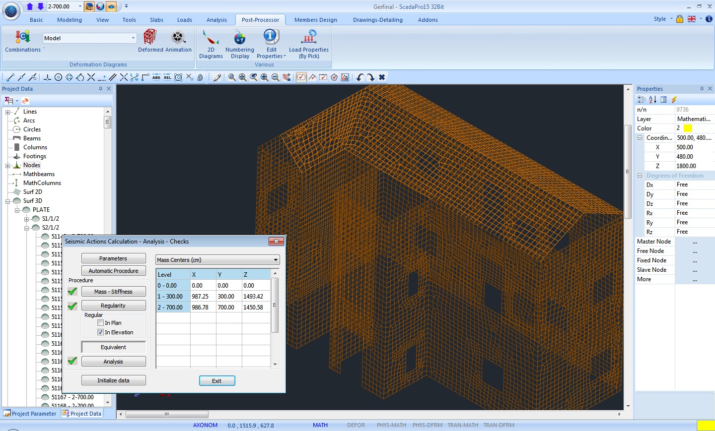
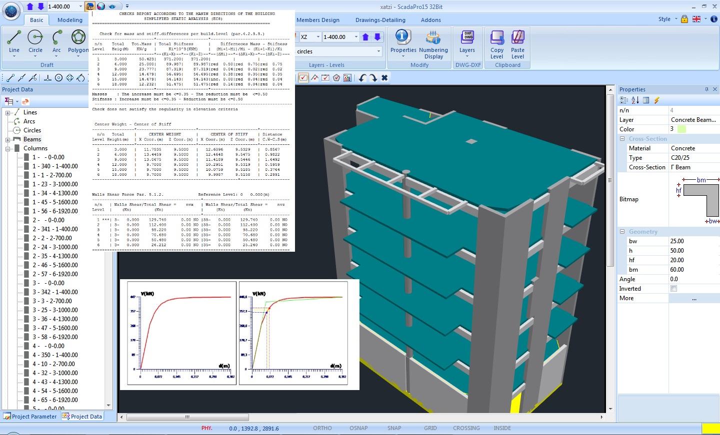
Analysis – Seismic design – Checks (EC8)
Full customization for repetitive analyses and result optimization. Try safely!
All the required by EC8 checks and the corresponding local regulations are presented in a way that is simple with complete oversight so that the user has a full overview of the entire structure.
In Scada Pro the user can choose the desired analysis method and regulations, and the program applies automatically the predefined parameters required by the regulations.
Furthermore, the ability to fully customize the environment, allows the user to try out solutions and validate the effects of each parameter based on the final results.
Of course, all the solutions produced, through the different scenarios provided by the software, are saved and are available at any time, for direct comparison.
Execution of multiple analyses with a single click. Versatility and infinite options for the user.
Scada Pro provides the user with the option to choose the desired analysis method in order to obtain the results fast and easy. It also provides the option to combine internal force values from different analysis methods!
Of course, all the load combinations are produced automatically, while allowing for editing whenever and however the user desires!
Scada Pro contains not only spectra design and checks according EC8 but also:
Spectra design and checks based on Greek Building Code (EAK, Old 1959-1984)
Seismic design criteria according SBC301 Saudi Building Code.
Spectra design and checks based on NTC2008 Italian Code.
Spectra design and checks based on NTC2008 Italian Code.
Spectra design and checks based on LGOM Polish Code.
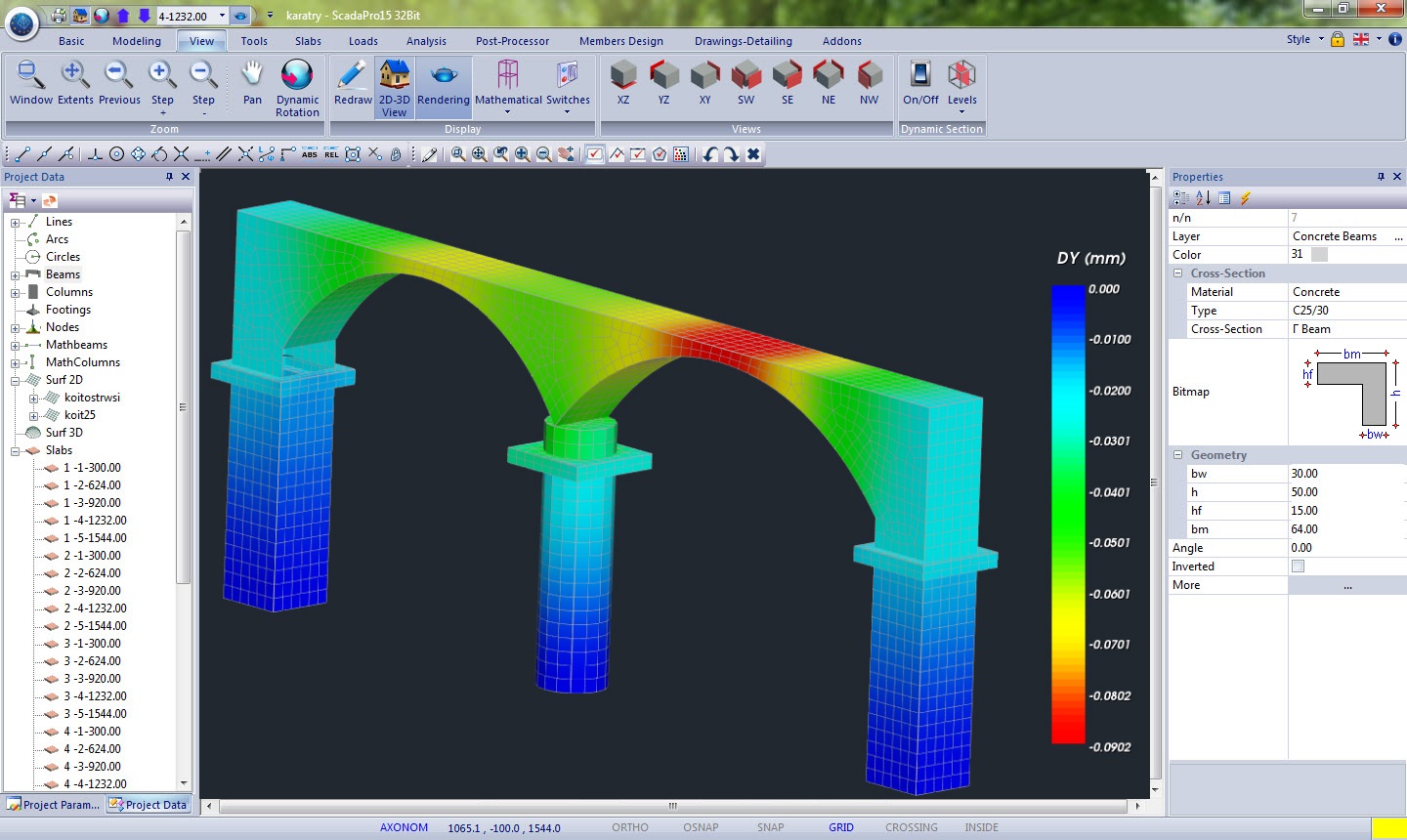
Results – Post Processing
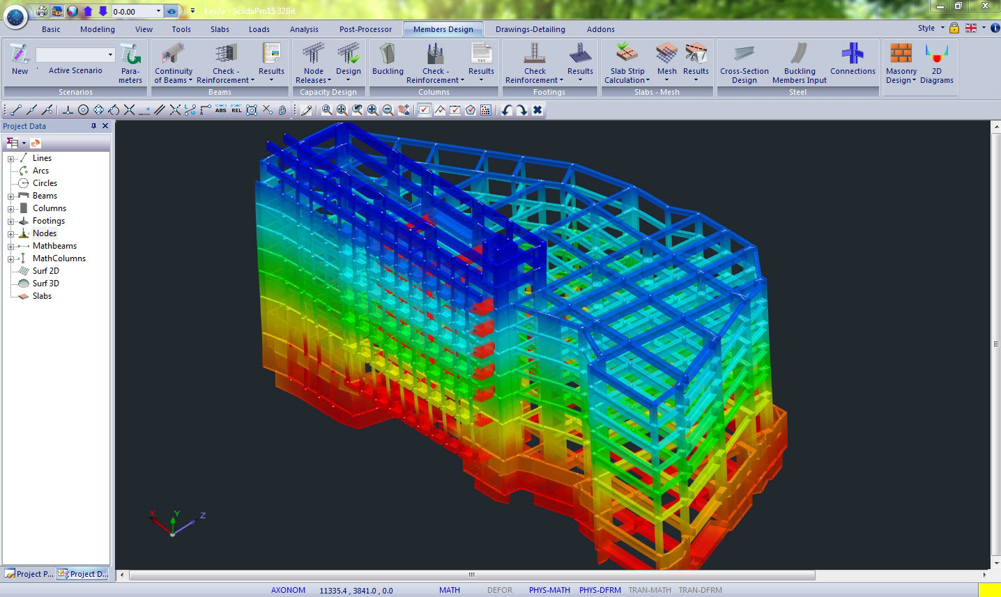
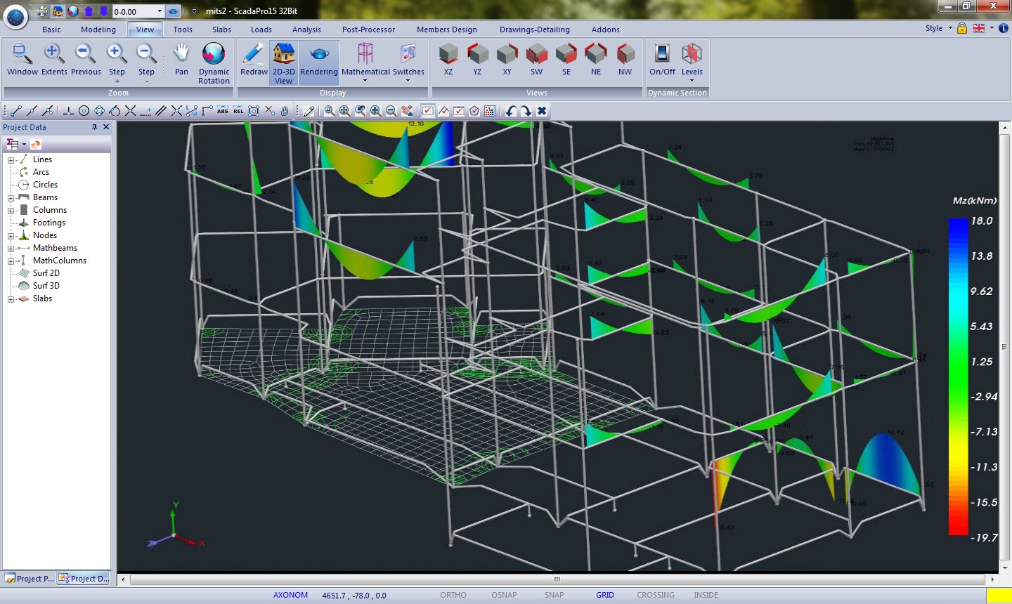
Three – dimensional visualization of the internal forces and deformed shape of the structure so that the user can have full oversight anytime.
The post processor section, through a rich and fluent graphical interface, provides the user all the tools to view the structure, colored diagrams from any internal force and loading, load combination or envelope.
All the user have to do is to choose the view scale and locate fast and easily the members developing the maximum forces or deformations.

The user can also view the deformed structure with motion in space for any static or dynamic loading and eigenmode.
Furthermore, the post processor section offers:
- Display of the results of internal forces, deformations and reinforcement of surface finite element in form of contour curves.
- Deformation state of structural model with movement in space for any load condition, combination or eigenvalue.
- Members’ diagrams, nodes displacements, plate element internal forces, slab strip diagrams view.
- Color display of intensive sizes on linear and surface elements, based on the sign.
- Display capability of the deformation values based on the color gradation.
Report of the project
User-friendly interface for the creation and editing of the report
In Scada Pro the user simply selects the sections, automatically created based on relevant regulations, to be included in the report of the project.
Simple tools allow the user to edit the report header and footer position chapters and create automatically the table of contents.
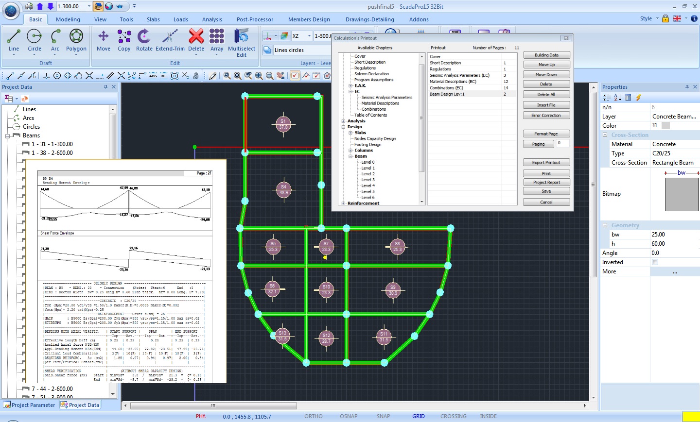
The report may be previewed before the user can save it for further editing in one of the following file formats: RTF, PDF, HTML, PPTX, XLSX.